


The E-Spin: Converting a retired dockless bike into a pedelec
 03-01-20, 05:41 PM
#1

www.theheadbadge.com
Thread Starter

Join Date: Sep 2005
Location: Southern Florida
Posts: 28,513
Bikes: https://www.theheadbadge.com
Mentioned: 124 Post(s)
Tagged: 0 Thread(s)
Quoted: 2422 Post(s)
Liked 4,390 Times
in
2,092 Posts
The E-Spin: Converting a retired dockless bike into a pedelec
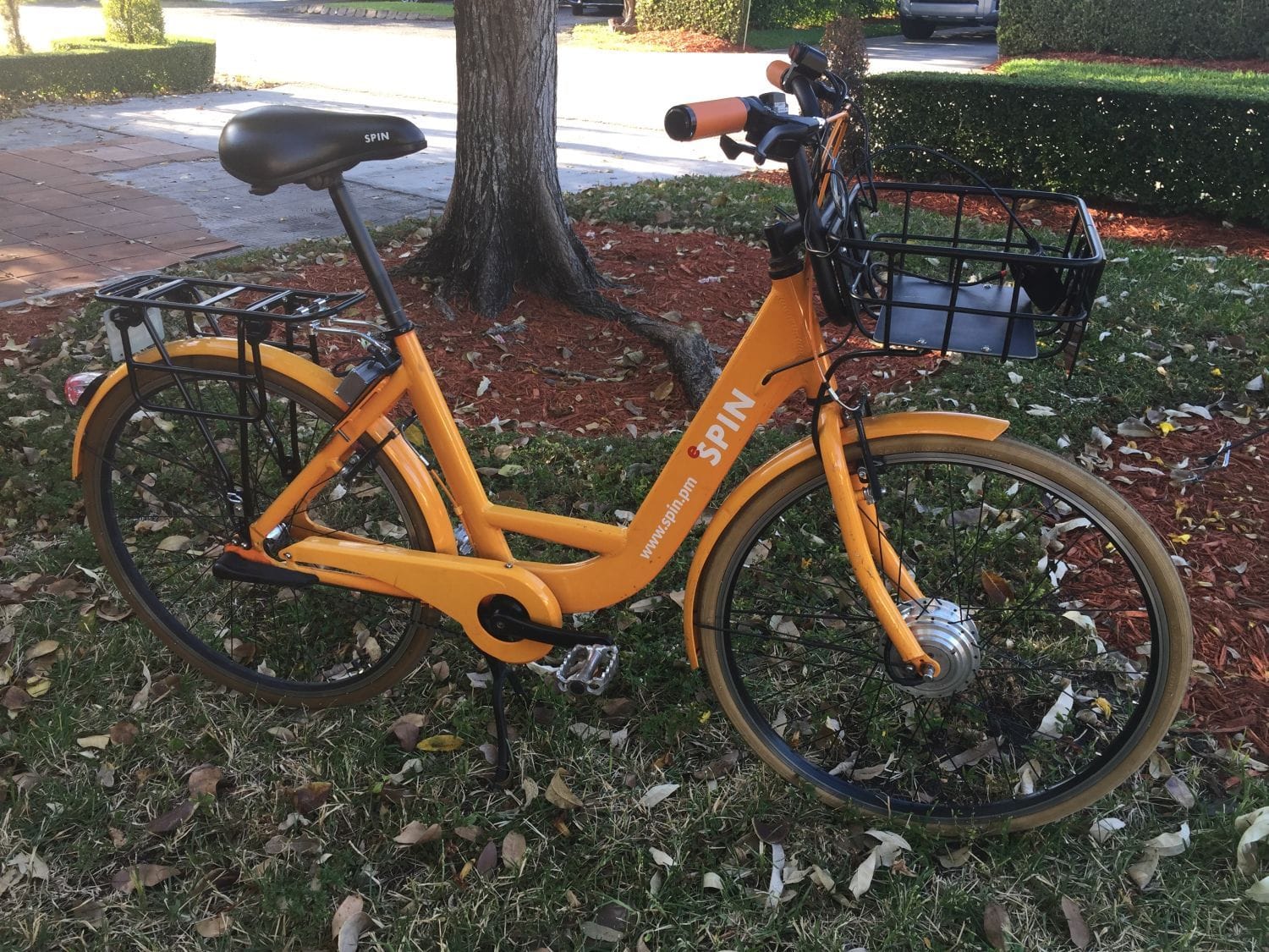
First, a bit of backstory: Back in December of last year, I was able to work out a huge donation with Spin, the bike share / scooter share company. Since they'd transitioned entirely to scooters in South Florida, they donated almost their entire fleet of 500+ bikes to my Bike Share Museum. With the help of a volunteer (urban_plan_b on Twitter), we fixed them up and distributed the retired bikes all around town to those in need. I've written about the whole thing here, for those curious about the whole story (even though this article is already out of date).
Long story short, my inspiration to contact Spin started with one particular bike I had seen many months prior near a friend's house - #7723417 . It later surfaced during the donation.
It was in need of some TLC, so I set it aside and ultimately made it into a nice 3-speed office commuter, with a few little special touches on it. And yes, Spin doesn't mind that I run it with numbers and all (though the lock has been deactivated and is no longer functional).
By the way, if you were expecting drop bars and carbon saddle rails in this thread...forget it - this thing weighs 41 pounds unladen, and a hell of a lot more when the panniers are full.
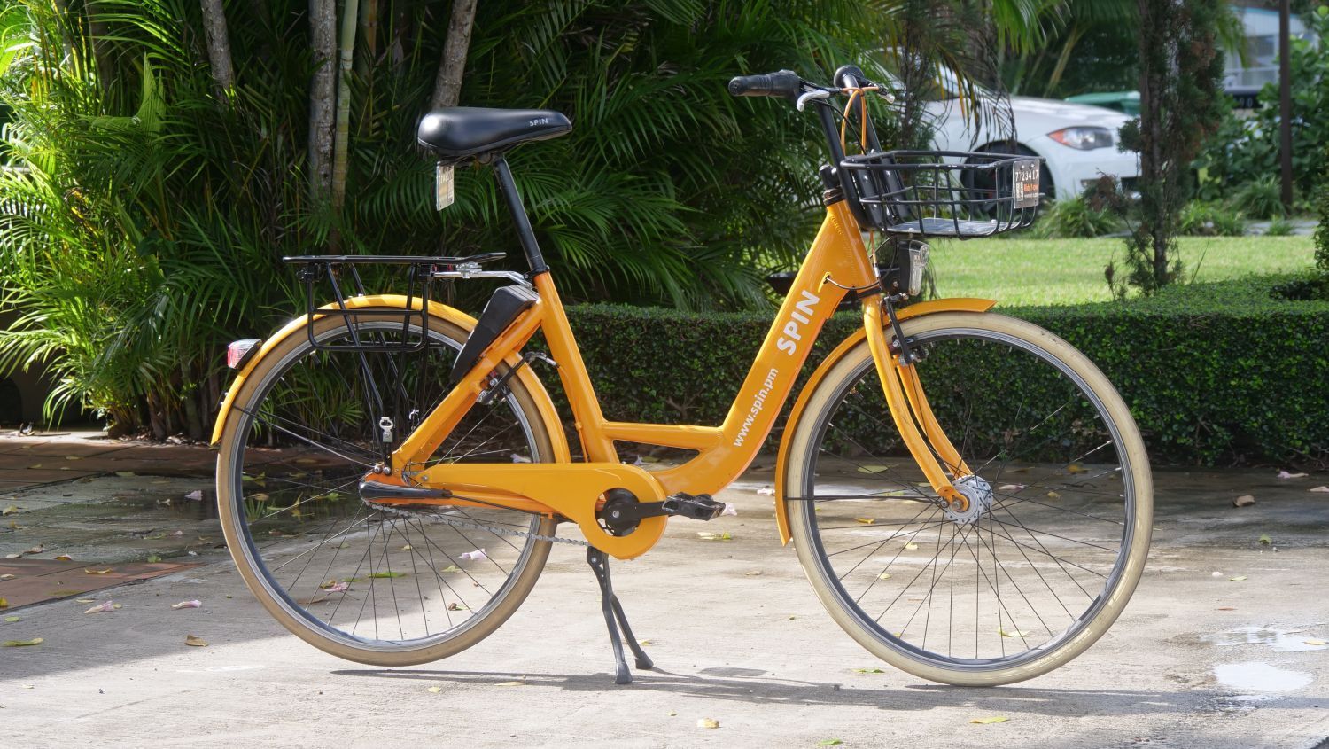
This is a second-generation model, with 26x1-3/8" wheels and conventional V-brakes. The subsequent Gen 3 models are a lot more like the typical dockless bike (26"/559 wheels, brakes at the hubs, etc).
That said, I'm also starting to use it during work to get from place to place and having a bit of assist would be quite nice.
Though I've never really tinkered with e-bike conversions before, I've already had an introduction to Bafang pedelecs and Bosch mid-drives and love both. Coincidentally, all of these have been bike share bikes (the Jump 5.0 and 5.5, the docked RideOn Miami pedelecs, and two variants of the Trek BCycle e-assist models). Though none of these are being donated anytime soon, I do like the idea of having a pedelec.
Better still, the idea of building a one on the Spin Gen 2 presents a pretty fun "what if?" scenario: Spin went straight from analog bicycles to scooters and never released an e-bike. Then I nabbed this on eBay:
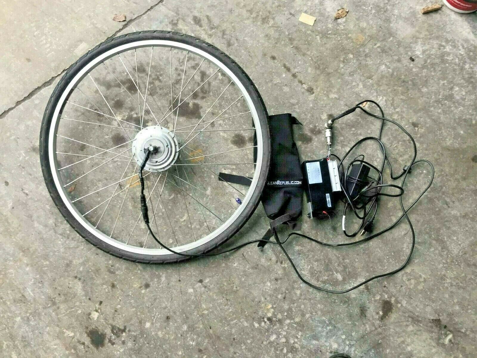
It's an 8FUN (Bafang) 24V / 250W front drive motor that's been put together with a bit too much electrical tape - but the price was ridiculously cheap. I tested the motor (sans battery - ran 24V straight to the controller) and it works too.
That's not to say it isn't without issues. The electrical tape was hiding a disaster of frayed wires underneath. Thankfully, no evidence of burnie burnie, so some careful soldering and heat shrink should settle this.

In the meantime, I have a spare Spin front rim that I'm going to de-lace for this hub - if I calculated the rim inner diameter correctly, I think I have the right spokes to put this hub straight into it.
I also ordered a Brainpower 24V/250W motor controller off Amazon with the additional leads for the PAS/hall sensor and brake lever cutouts. It'll replace the eBay controller which is literally a on/off button.
More soon.
-Kurt
Long story short, my inspiration to contact Spin started with one particular bike I had seen many months prior near a friend's house - #7723417 . It later surfaced during the donation.
It was in need of some TLC, so I set it aside and ultimately made it into a nice 3-speed office commuter, with a few little special touches on it. And yes, Spin doesn't mind that I run it with numbers and all (though the lock has been deactivated and is no longer functional).
By the way, if you were expecting drop bars and carbon saddle rails in this thread...forget it - this thing weighs 41 pounds unladen, and a hell of a lot more when the panniers are full.
This is a second-generation model, with 26x1-3/8" wheels and conventional V-brakes. The subsequent Gen 3 models are a lot more like the typical dockless bike (26"/559 wheels, brakes at the hubs, etc).
That said, I'm also starting to use it during work to get from place to place and having a bit of assist would be quite nice.
Though I've never really tinkered with e-bike conversions before, I've already had an introduction to Bafang pedelecs and Bosch mid-drives and love both. Coincidentally, all of these have been bike share bikes (the Jump 5.0 and 5.5, the docked RideOn Miami pedelecs, and two variants of the Trek BCycle e-assist models). Though none of these are being donated anytime soon, I do like the idea of having a pedelec.
Better still, the idea of building a one on the Spin Gen 2 presents a pretty fun "what if?" scenario: Spin went straight from analog bicycles to scooters and never released an e-bike. Then I nabbed this on eBay:
It's an 8FUN (Bafang) 24V / 250W front drive motor that's been put together with a bit too much electrical tape - but the price was ridiculously cheap. I tested the motor (sans battery - ran 24V straight to the controller) and it works too.
That's not to say it isn't without issues. The electrical tape was hiding a disaster of frayed wires underneath. Thankfully, no evidence of burnie burnie, so some careful soldering and heat shrink should settle this.
In the meantime, I have a spare Spin front rim that I'm going to de-lace for this hub - if I calculated the rim inner diameter correctly, I think I have the right spokes to put this hub straight into it.
I also ordered a Brainpower 24V/250W motor controller off Amazon with the additional leads for the PAS/hall sensor and brake lever cutouts. It'll replace the eBay controller which is literally a on/off button.
More soon.
-Kurt
__________________


Last edited by cudak888; 06-13-20 at 11:27 PM.

Likes For cudak888:
03-03-20, 01:21 AM
#2
Senior Member
I love repurposed projects!
You didn't think about just using a cheap $25 Chinese controller? They will ignore missing hall effect sensors, although are a little noisier on acceleration with no halls.
Also you don't need power to test hub motors, you just short any 2 of the leads together and spin the wheel, if it hard to turn, thats good. Do the same with either one of the leads you already did and the one you didn't, again, it should be hard to spin.
Last edited by spinnanz; 03-03-20 at 01:26 AM.
Likes For spinnanz:
03-03-20, 06:21 AM
#3
www.theheadbadge.com
Thread Starter
Join Date: Sep 2005
Location: Southern Florida
Posts: 28,513
Bikes: https://www.theheadbadge.com
Mentioned: 124 Post(s)
Tagged: 0 Thread(s)
Quoted: 2422 Post(s)
Liked 4,390 Times
in
2,092 Posts
I love repurposed projects!
You didn't think about just using a cheap $25 Chinese controller? They will ignore missing hall effect sensors, although are a little noisier on acceleration with no halls.
Also you don't need power to test hub motors, you just short any 2 of the leads together and spin the wheel, if it hard to turn, thats good. Do the same with either one of the leads you already did and the one you didn't, again, it should be hard to spin.
You didn't think about just using a cheap $25 Chinese controller? They will ignore missing hall effect sensors, although are a little noisier on acceleration with no halls.
Also you don't need power to test hub motors, you just short any 2 of the leads together and spin the wheel, if it hard to turn, thats good. Do the same with either one of the leads you already did and the one you didn't, again, it should be hard to spin.
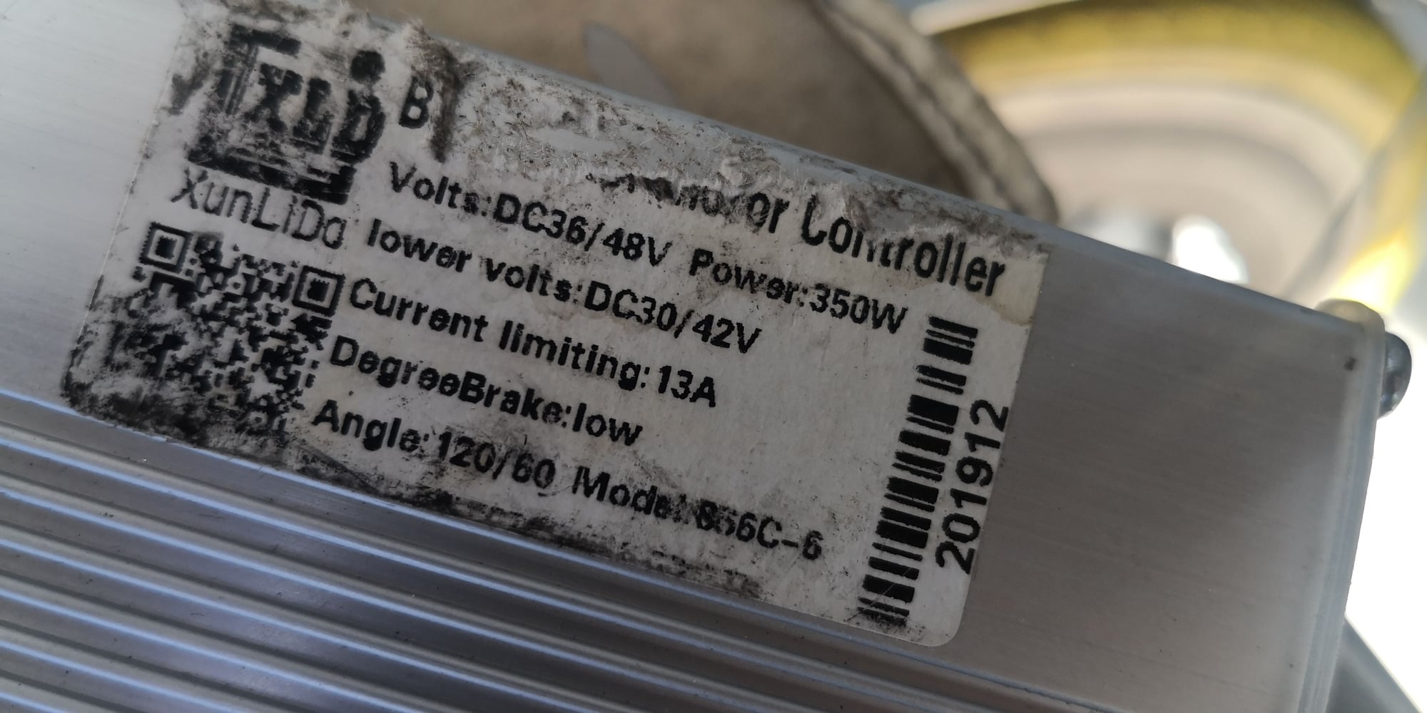
The new brushless controller from Amazon (stock pic below) was $10.69 (it fluctuates between that and $25.64 depending on who's selling it), so I'm not particularly upset at the cost
 . I just hope it works with the Bafang/8FUN hub.
I hope it'll run with just the
I'll remember that trick for the hub, but it really wasn't difficult to take a G-scale model railroad controller, set the polarity right, and run 24V directly to the motor controller. That way, I know the original stock system is working as well.
I'm crossing my fingers there's enough wire in the stock harness that I can just re-use it for through-the-frame cable routing. Have yet to find a source for 3-conductor wire that seems to be correct. Not to mention that I'd like to find a better plug to solder into the hub and wiring harness - this one is huge and has no obvious weather seal.
-Kurt
__________________
Last edited by cudak888; 03-05-20 at 10:43 PM.
03-03-20, 12:15 PM
#4
Senior Member
This controllers are usually pretty good for the price. If you power it up, with those "intelegant Id" wires joined it should automatically detect what you do and don't have connected and work from that. It's also used to program in the direction you went the hub to spin.
03-03-20, 10:15 PM
#5
www.theheadbadge.com
Thread Starter
Join Date: Sep 2005
Location: Southern Florida
Posts: 28,513
Bikes: https://www.theheadbadge.com
Mentioned: 124 Post(s)
Tagged: 0 Thread(s)
Quoted: 2422 Post(s)
Liked 4,390 Times
in
2,092 Posts
This controllers are usually pretty good for the price. If you power it up, with those "intelegant Id" wires joined it should automatically detect what you do and don't have connected and work from that. It's also used to program in the direction you went the hub to spin.
Is there any PAS you'd recommend, incidentally? The ones with the clip-on sensor wheel that are all over Amazon appear really questionable (and those that fasten to the BB would also require that I swap out the existing BB for a Shimano UN-55 which has a flange on the adjustable cup.
I did run across this one, but I have no idea if it is compatible: https://www.ebikes.ca/shop/electric-.../pas-24p.html#
-Kurt
__________________
03-03-20, 11:17 PM
#6
Senior Member
I went with this PAS but I removed the sensor and made an "L" bracket for it, this was then screwed to the frame.
My controller will work off either the PAS or throttle (or both) and is the same brand as yours, so would assume yours can too.
Mine has a display so I can use that to edit some settings. I've set my PAS to kick in after 3 rotations of the crank, from factory it kicked in at half a turn. The main reason for this is that when powered up, if the bike is pushed backwards (fast enough) it can power up the motor because the crank rotates.
Last edited by spinnanz; 03-03-20 at 11:40 PM.
03-04-20, 06:09 AM
#7
www.theheadbadge.com
Thread Starter
Join Date: Sep 2005
Location: Southern Florida
Posts: 28,513
Bikes: https://www.theheadbadge.com
Mentioned: 124 Post(s)
Tagged: 0 Thread(s)
Quoted: 2422 Post(s)
Liked 4,390 Times
in
2,092 Posts
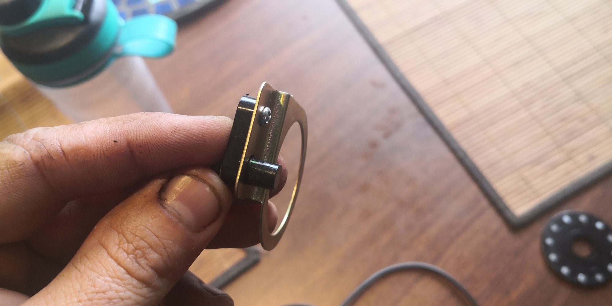
That's similar to the sensor I've seen all through Amazon. I don't mind the ring that holds the sensor (though I'm not that keen on the sensor disc), but sure enough, I'm probably going to have to swap the BB just to get an adjustable cup that'll hold it in place.
I wonder if swapping it to the drive side would work, if there's enough space on the spindle.
EDIT: No reason why it shouldn't...
EDIT #2 : Just ordered this 8FUN PAS from Amazon:

Which plug was your display hooked up to? Or is that function unique to your controller?
-Kurt
I wonder if swapping it to the drive side would work, if there's enough space on the spindle.
EDIT: No reason why it shouldn't...
EDIT #2 : Just ordered this 8FUN PAS from Amazon:
Which plug was your display hooked up to? Or is that function unique to your controller?
-Kurt
__________________
Last edited by cudak888; 03-04-20 at 06:46 AM.
03-04-20, 10:55 AM
#8
Senior Member
I've fitted my sensor to the drive side, only for the fact I didn't want it to be seen easily.
The display I have is a S866, it's a generic one that fits most Chinese controllers with a 5 pin plug. From memory my controller and display was $50nz/�25uk.

The display I have is a S866, it's a generic one that fits most Chinese controllers with a 5 pin plug. From memory my controller and display was $50nz/�25uk.
Likes For spinnanz:
03-04-20, 09:31 PM
#9
www.theheadbadge.com
Thread Starter
Join Date: Sep 2005
Location: Southern Florida
Posts: 28,513
Bikes: https://www.theheadbadge.com
Mentioned: 124 Post(s)
Tagged: 0 Thread(s)
Quoted: 2422 Post(s)
Liked 4,390 Times
in
2,092 Posts
From what I can see, the Brainpower box I have (LSL123) doesn't have the five-pin plug for the LCD output. Oh well...
-Kurt
__________________
03-04-20, 09:52 PM
#10
Senior Member
From what I've read your brain box is almost the same as mine, less the plug for the display, I guess yours is just pre-programmed
Likes For spinnanz:
03-04-20, 11:07 PM
#11
www.theheadbadge.com
Thread Starter
Join Date: Sep 2005
Location: Southern Florida
Posts: 28,513
Bikes: https://www.theheadbadge.com
Mentioned: 124 Post(s)
Tagged: 0 Thread(s)
Quoted: 2422 Post(s)
Liked 4,390 Times
in
2,092 Posts
Mine is the 24V / 250W variant - a bit different:

__________________
03-04-20, 11:25 PM
#12
Senior Member
Likes For spinnanz:
03-05-20, 10:51 PM
#13
www.theheadbadge.com
Thread Starter
Join Date: Sep 2005
Location: Southern Florida
Posts: 28,513
Bikes: https://www.theheadbadge.com
Mentioned: 124 Post(s)
Tagged: 0 Thread(s)
Quoted: 2422 Post(s)
Liked 4,390 Times
in
2,092 Posts
Also worried that the controller might not work now: The Bafang motor has only those three wires and no hall sensor on it (my mistake - kept confusing the PAS with a hall sensor). The controller does have a hall sensor. Fingers crossed that it can work without it...
-Kurt
__________________
03-06-20, 05:27 PM
#14
Senior Member
Honestly, I don't even know what the voltage of the battery pack is yet. Might have to undo the shrink wrap just to verify it along with the type of Li-Ions in there. Pretty sure the "battery charger" provided from the eBay seller is just a random 19V power supply and not a real charger either.
Also worried that the controller might not work now: The Bafang motor has only those three wires and no hall sensor on it (my mistake - kept confusing the PAS with a hall sensor). The controller does have a hall sensor. Fingers crossed that it can work without it...
-Kurt
Also worried that the controller might not work now: The Bafang motor has only those three wires and no hall sensor on it (my mistake - kept confusing the PAS with a hall sensor). The controller does have a hall sensor. Fingers crossed that it can work without it...
-Kurt
Last edited by spinnanz; 03-06-20 at 08:58 PM.
03-06-20, 08:32 PM
#15
www.theheadbadge.com
Thread Starter
Join Date: Sep 2005
Location: Southern Florida
Posts: 28,513
Bikes: https://www.theheadbadge.com
Mentioned: 124 Post(s)
Tagged: 0 Thread(s)
Quoted: 2422 Post(s)
Liked 4,390 Times
in
2,092 Posts
Should prove interesting. Laced up the wheel this evening, still have to sort out the wiring. Might email ebikes.ca to see if they have a factory replacement grommet for the cable entry (rather than 3D print a replacement).
-Kurt
__________________
03-12-20, 07:47 PM
#16
www.theheadbadge.com
Thread Starter
Join Date: Sep 2005
Location: Southern Florida
Posts: 28,513
Bikes: https://www.theheadbadge.com
Mentioned: 124 Post(s)
Tagged: 0 Thread(s)
Quoted: 2422 Post(s)
Liked 4,390 Times
in
2,092 Posts
The conversion begins. I test fit the newly-laced front wheel to find out whether I should work a 90 degree bend into the 3D-printed replacement grommet for the front hub.
Answer: Yes. The dropout doesn't leave much room for the cable exit. Granted, I haven't done diddly to fix the wiring, but I also wanted to figure out how long a cable run I'll need.

I also installed the brake levers with throttle cutouts. These have Julet connectors and the controller has JST-SMs. I'll probably replace the controller's connections with Julets.
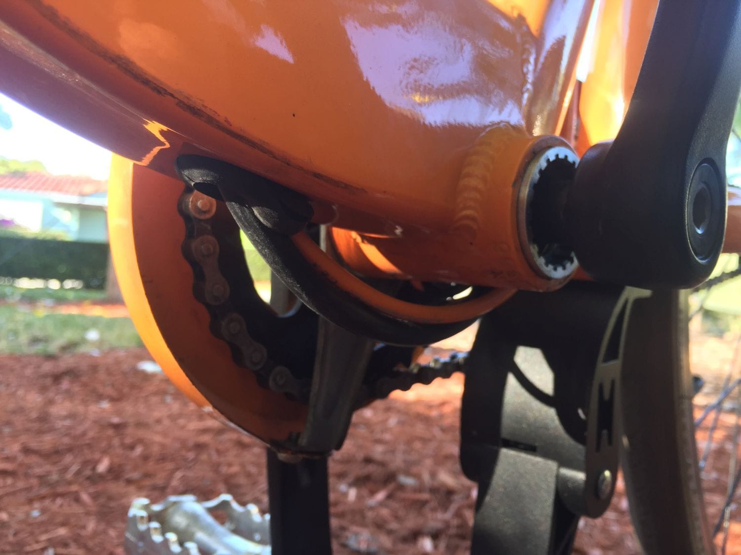
If you look closely, you'll see the PAS sensor installed:

...and up close. I had to clearance a bit of the chainguard mount, but it adapts very nicely. I know I have to reverse the sensor itself so it points in the direction of crank rotation.
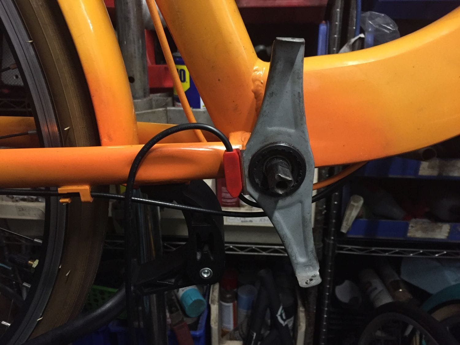
For better or worse, it looks as if I'll have to replace the BB in all of this. The magnet ring just barely fits, but the crankset - when installed - pushes the ring inboard enough to rub against the sensor.

-Kurt
Answer: Yes. The dropout doesn't leave much room for the cable exit. Granted, I haven't done diddly to fix the wiring, but I also wanted to figure out how long a cable run I'll need.
I also installed the brake levers with throttle cutouts. These have Julet connectors and the controller has JST-SMs. I'll probably replace the controller's connections with Julets.
If you look closely, you'll see the PAS sensor installed:
...and up close. I had to clearance a bit of the chainguard mount, but it adapts very nicely. I know I have to reverse the sensor itself so it points in the direction of crank rotation.
For better or worse, it looks as if I'll have to replace the BB in all of this. The magnet ring just barely fits, but the crankset - when installed - pushes the ring inboard enough to rub against the sensor.
-Kurt
__________________
03-13-20, 05:50 PM
#17
www.theheadbadge.com
Thread Starter
Join Date: Sep 2005
Location: Southern Florida
Posts: 28,513
Bikes: https://www.theheadbadge.com
Mentioned: 124 Post(s)
Tagged: 0 Thread(s)
Quoted: 2422 Post(s)
Liked 4,390 Times
in
2,092 Posts
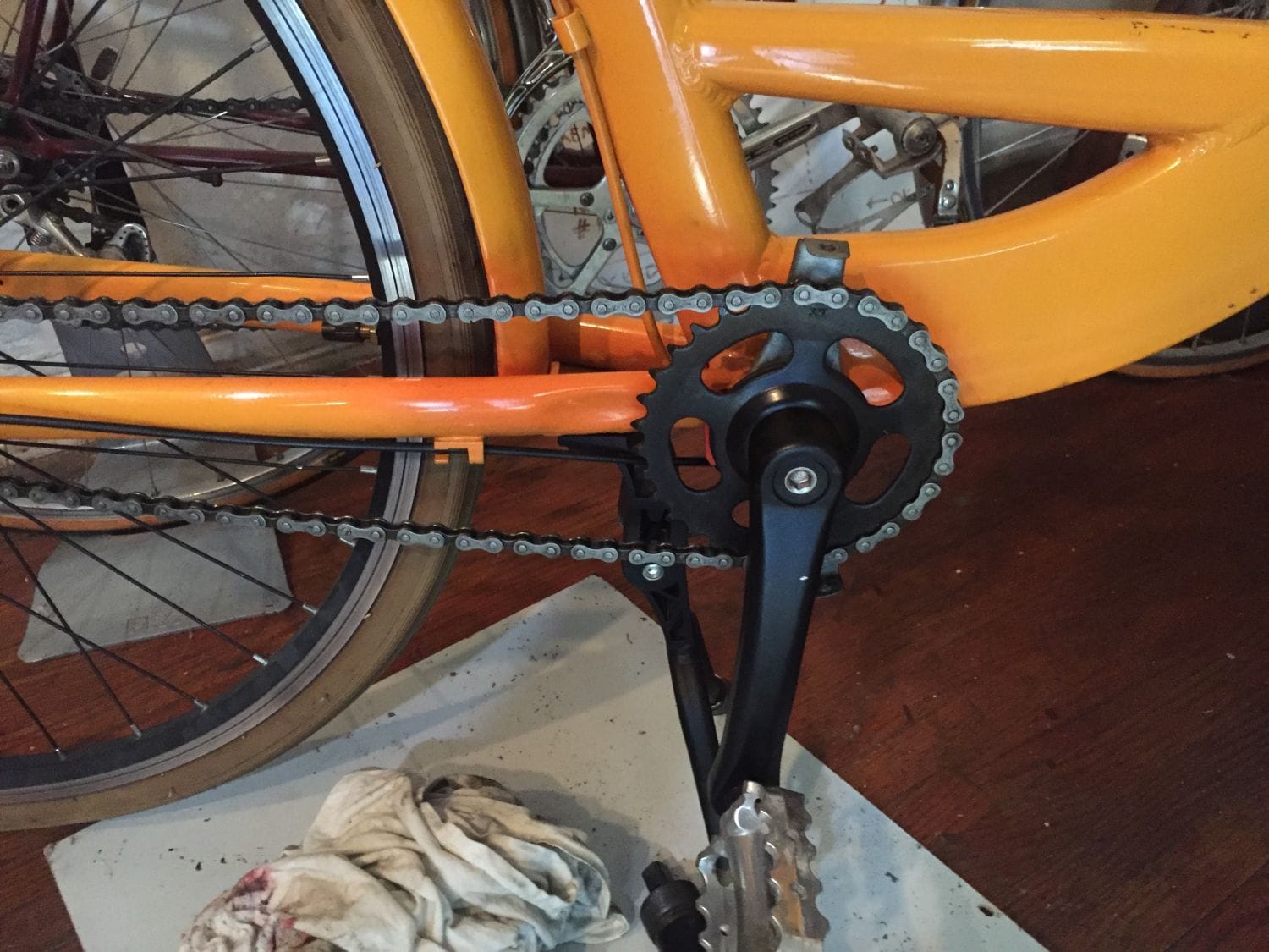
PAS sensor has been reoriented upwards and the cable run through the frame. If it looks a bit wonky, it's because the BB is loose in the shell.
The factory BB measures out to 124.5mm (marked 124mm), so I ordered a 127.5mm Shimano UN55 from Amazon. We'll see if the extra 3mm does the trick and whether chainline remains acceptable.

-Kurt
The factory BB measures out to 124.5mm (marked 124mm), so I ordered a 127.5mm Shimano UN55 from Amazon. We'll see if the extra 3mm does the trick and whether chainline remains acceptable.
-Kurt
__________________
03-14-20, 09:36 AM
#18
www.theheadbadge.com
Thread Starter
Join Date: Sep 2005
Location: Southern Florida
Posts: 28,513
Bikes: https://www.theheadbadge.com
Mentioned: 124 Post(s)
Tagged: 0 Thread(s)
Quoted: 2422 Post(s)
Liked 4,390 Times
in
2,092 Posts
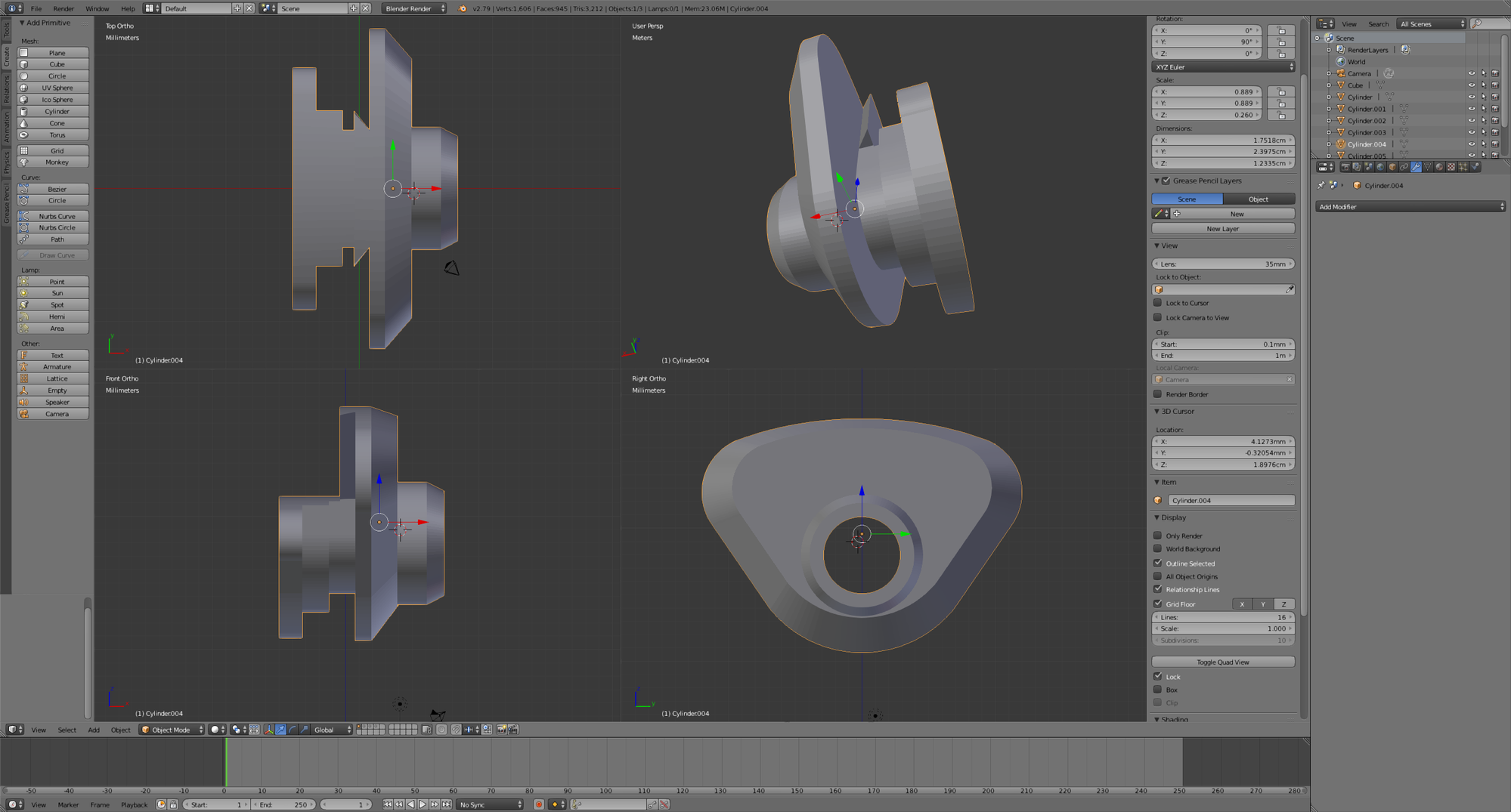
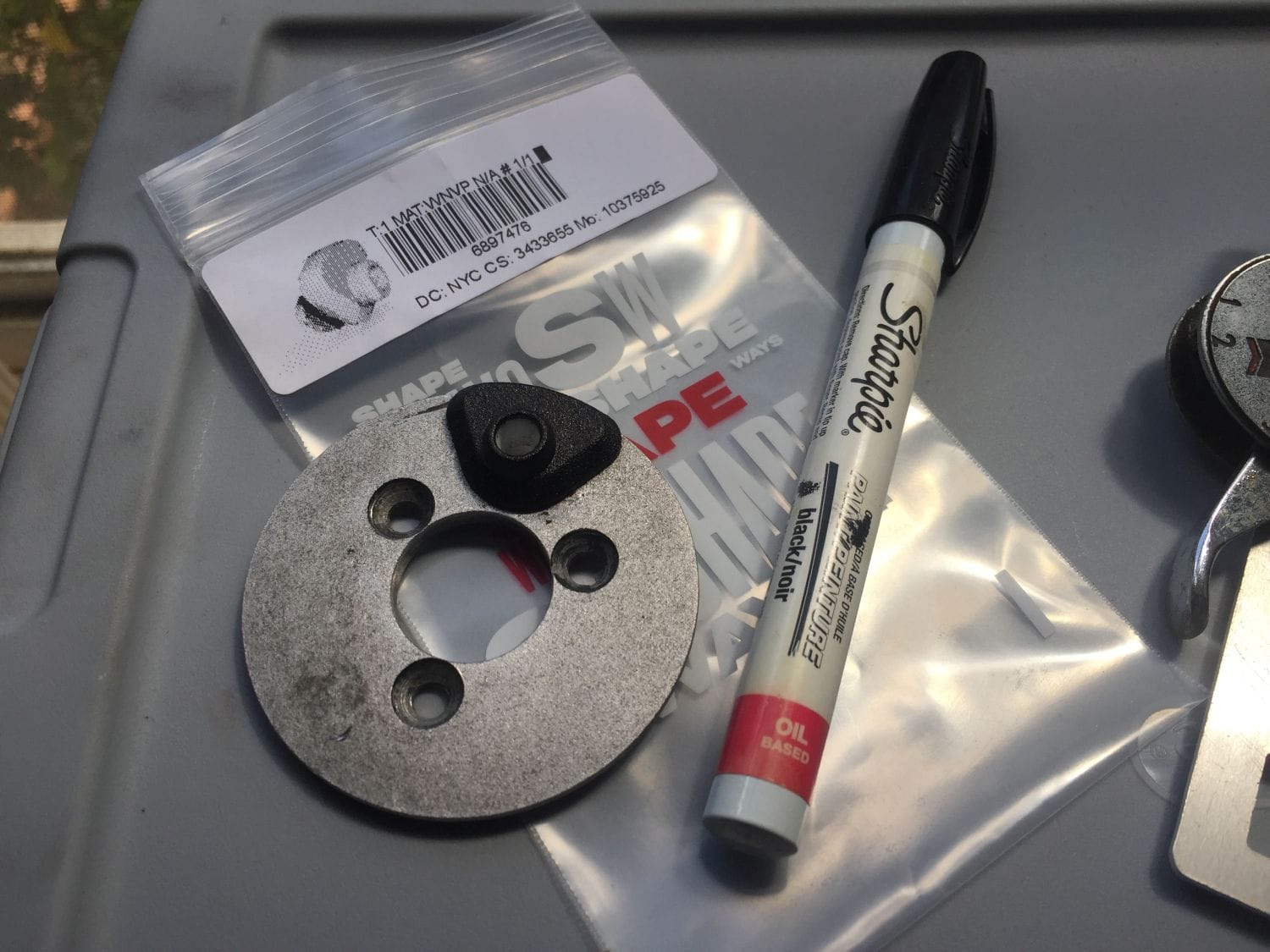
Working on designing the 3D printed replacement grommet now. To get the cutout right, it's easiest to replicate the hub cover plate, then subtract its shape out of the grommet (to be designed) to get the shape right.

-Kurt
-Kurt
__________________
Likes For cudak888:
03-14-20, 09:41 PM
#19
www.theheadbadge.com
Thread Starter
Join Date: Sep 2005
Location: Southern Florida
Posts: 28,513
Bikes: https://www.theheadbadge.com
Mentioned: 124 Post(s)
Tagged: 0 Thread(s)
Quoted: 2422 Post(s)
Liked 4,390 Times
in
2,092 Posts
This should do...
-Kurt
-Kurt
__________________
03-15-20, 06:39 PM
#20
www.theheadbadge.com
Thread Starter
Join Date: Sep 2005
Location: Southern Florida
Posts: 28,513
Bikes: https://www.theheadbadge.com
Mentioned: 124 Post(s)
Tagged: 0 Thread(s)
Quoted: 2422 Post(s)
Liked 4,390 Times
in
2,092 Posts
The Shimano 127.5mm UN55 bottom bracket arrived today. There's enough space between the ring and the sensor now, but the magnet ring bowed on the Shimano BB shaft - seems as if the Shimano shaft is thicker than the ring was designed for. I'll probably pull it off later, shave off a bit from the ID, and remount it.
At any rate, it disappears nicely.


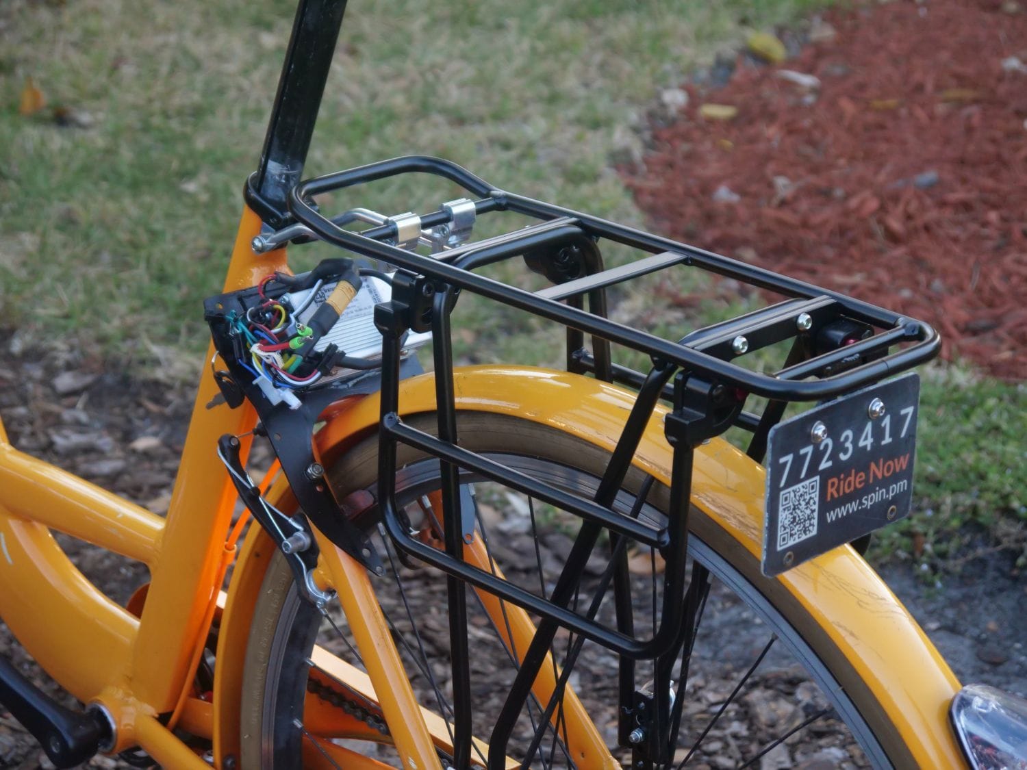
Also chopped up a spare battery/GPS box and test-mounted the motor controller. I have two Z910 extension cables on the way and will wire them into this assembly.

-Kurt
At any rate, it disappears nicely.
Also chopped up a spare battery/GPS box and test-mounted the motor controller. I have two Z910 extension cables on the way and will wire them into this assembly.
-Kurt
__________________
03-21-20, 06:12 PM
#21
www.theheadbadge.com
Thread Starter
Join Date: Sep 2005
Location: Southern Florida
Posts: 28,513
Bikes: https://www.theheadbadge.com
Mentioned: 124 Post(s)
Tagged: 0 Thread(s)
Quoted: 2422 Post(s)
Liked 4,390 Times
in
2,092 Posts
The 3D printed grommet has arrived. It needed a bit of trimming - unfortunately the tolerances of this material aren't that great - but it fits well and looks good too:

The rough white plastic is a magnet for dirt and whatever happens to be on your fingers, so I decided to experiment painting it with an oil-based paint pen. Worked perfectly. Should do well when I invariably have to bore out the cable entrance hole to fit the replacement wires.
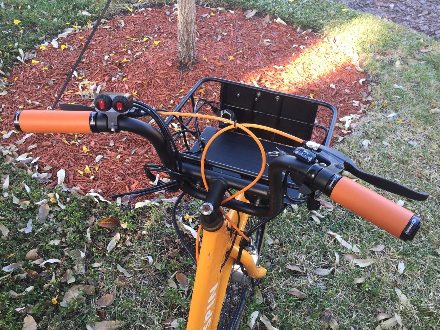
I also fitted some switches to the handlebar for power cutout and (eventually) the lighting. Admittedly, half of the fun is just having these James Bond buttons in the first place.
I had to cut the locking grip down in length for this. The slicing doesn't look all that great, but it'll do.

I also received some silicone insulated 15 AWG / 3 conductor wire to connect the controller to the motor - I'm throwing the HiGo Z910 idea out the window. This stuff is fairly thick, but I'd rather be on the safe side. I have MT60 connectors to put at the ends, just waiting on the heatshrink tubing.
...and the rat's nest. The PAS sensor wiring doesn't add up with the same plug on the controller, so this should be interesting. Googlefu time.

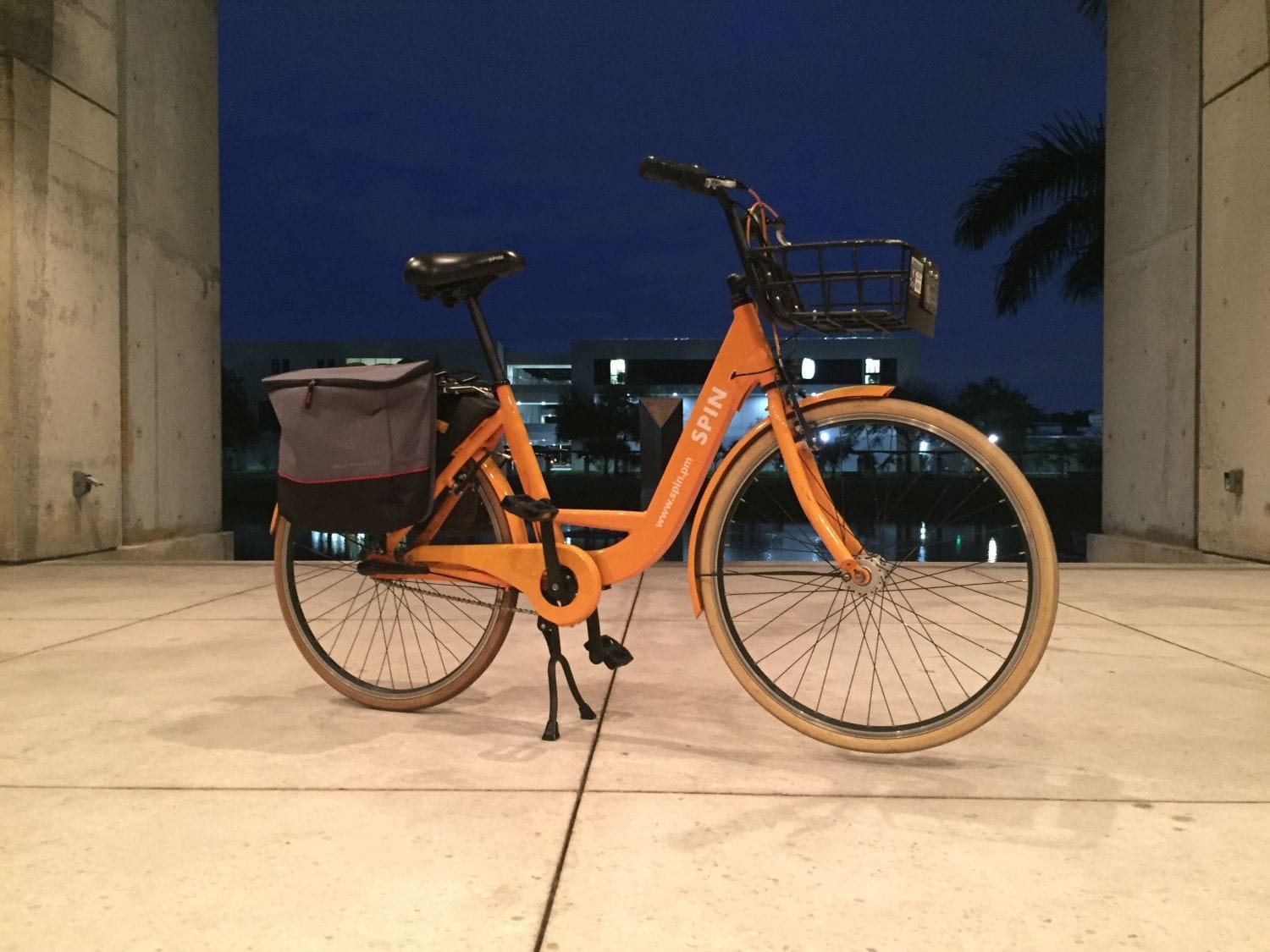
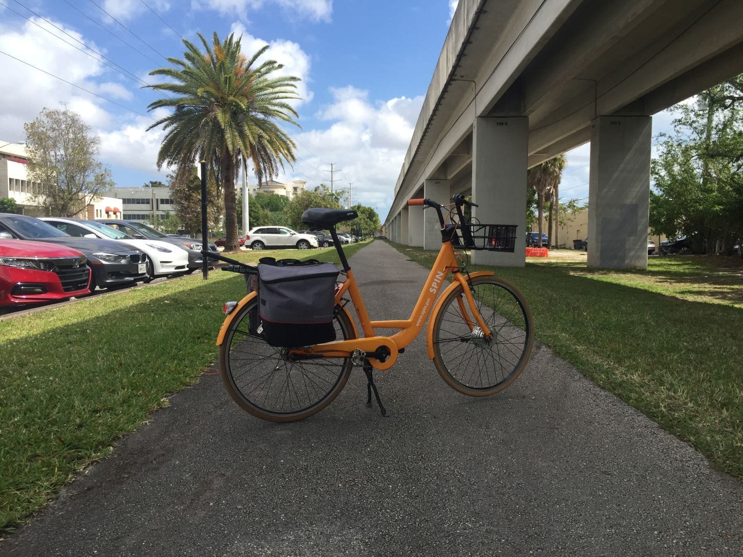
Incidentally, I buttoned it up just enough to use it earlier in the month when I needed to drag some camera equipment out to the local M-Path. Captured some pictures:

-Kurt
The rough white plastic is a magnet for dirt and whatever happens to be on your fingers, so I decided to experiment painting it with an oil-based paint pen. Worked perfectly. Should do well when I invariably have to bore out the cable entrance hole to fit the replacement wires.
I also fitted some switches to the handlebar for power cutout and (eventually) the lighting. Admittedly, half of the fun is just having these James Bond buttons in the first place.
I had to cut the locking grip down in length for this. The slicing doesn't look all that great, but it'll do.
I also received some silicone insulated 15 AWG / 3 conductor wire to connect the controller to the motor - I'm throwing the HiGo Z910 idea out the window. This stuff is fairly thick, but I'd rather be on the safe side. I have MT60 connectors to put at the ends, just waiting on the heatshrink tubing.
...and the rat's nest. The PAS sensor wiring doesn't add up with the same plug on the controller, so this should be interesting. Googlefu time.
Incidentally, I buttoned it up just enough to use it earlier in the month when I needed to drag some camera equipment out to the local M-Path. Captured some pictures:
-Kurt
__________________
03-23-20, 08:22 PM
#22
www.theheadbadge.com
Thread Starter
Join Date: Sep 2005
Location: Southern Florida
Posts: 28,513
Bikes: https://www.theheadbadge.com
Mentioned: 124 Post(s)
Tagged: 0 Thread(s)
Quoted: 2422 Post(s)
Liked 4,390 Times
in
2,092 Posts
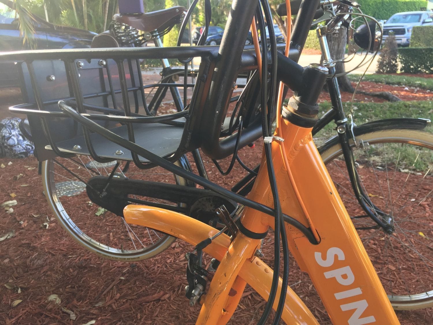
It's coming together! I soldered all the MT60 connectors and fixed the wrecked wiring at the motor over the weekend.
The polished 8FUN motor complements the Sturmey SRF-3 even better than the silver-painted Sturmey HDS-12 generator that used to sit up front.
Not perfect, but a heck of a lot better than before! There is no contact between the dropout and the wire, despite what it may look like in the photo.

The rat's nest is still a rat's nest, but it's purpose is becoming a bit better defined now. Still not sure where I want to route the positive and negative battery leads, especially as I still have to run the cutout to the handlebars (and might do so with a relay so I'm not running all the battery's power up to the handlebars and back just for the on/off switch). A fairly large XT90 connector is on the menu for this.

When I first powered it up in the bike stand (off a 24V transformer), I found that the PAS sensor was activating only when backpedaled. I had to reverse the disc's orientation from its marked direction of rotation. Perhaps flipping the sensor around on its mount really didn't do anything. Whatever the case, it worked (I even matched up the PAS wiring from controller to sensor correctly on the first go, despite the color and pinout differences!) and the motor is now spinning up on the new motor controller.
Still a lot to sort out here. Unfortunately, the brake levers are the powered magnet type, not the simple on/off switch - and I happen to like how they feel. I'll probably regret the extra work to adapt them to this system, but I'll see if I can make them work.
The Sturmey-Archer DLS30 shifter arrived too - I'm really looking forward to trying it out. Hated the twist shifter, which is still dangling away in the basket there. I wanted to use an original Sturmey thumb shifter, but the fairly wide and flush design made positioning near the brake lever difficult. This seems like the perfect modern alternative. Just waiting on the color matched shift housing to button it up.

Love how the original headlight wiring braze-ons work perfectly to hide the motor wires.

-Kurt
The polished 8FUN motor complements the Sturmey SRF-3 even better than the silver-painted Sturmey HDS-12 generator that used to sit up front.
Not perfect, but a heck of a lot better than before! There is no contact between the dropout and the wire, despite what it may look like in the photo.
The rat's nest is still a rat's nest, but it's purpose is becoming a bit better defined now. Still not sure where I want to route the positive and negative battery leads, especially as I still have to run the cutout to the handlebars (and might do so with a relay so I'm not running all the battery's power up to the handlebars and back just for the on/off switch). A fairly large XT90 connector is on the menu for this.
When I first powered it up in the bike stand (off a 24V transformer), I found that the PAS sensor was activating only when backpedaled. I had to reverse the disc's orientation from its marked direction of rotation. Perhaps flipping the sensor around on its mount really didn't do anything. Whatever the case, it worked (I even matched up the PAS wiring from controller to sensor correctly on the first go, despite the color and pinout differences!) and the motor is now spinning up on the new motor controller.
Still a lot to sort out here. Unfortunately, the brake levers are the powered magnet type, not the simple on/off switch - and I happen to like how they feel. I'll probably regret the extra work to adapt them to this system, but I'll see if I can make them work.
The Sturmey-Archer DLS30 shifter arrived too - I'm really looking forward to trying it out. Hated the twist shifter, which is still dangling away in the basket there. I wanted to use an original Sturmey thumb shifter, but the fairly wide and flush design made positioning near the brake lever difficult. This seems like the perfect modern alternative. Just waiting on the color matched shift housing to button it up.
Love how the original headlight wiring braze-ons work perfectly to hide the motor wires.
-Kurt
__________________
03-29-20, 05:29 PM
#23
www.theheadbadge.com
Thread Starter
Join Date: Sep 2005
Location: Southern Florida
Posts: 28,513
Bikes: https://www.theheadbadge.com
Mentioned: 124 Post(s)
Tagged: 0 Thread(s)
Quoted: 2422 Post(s)
Liked 4,390 Times
in
2,092 Posts
It's running! Have some new pictures with about 60% of the cable management installed on it - will post that later:
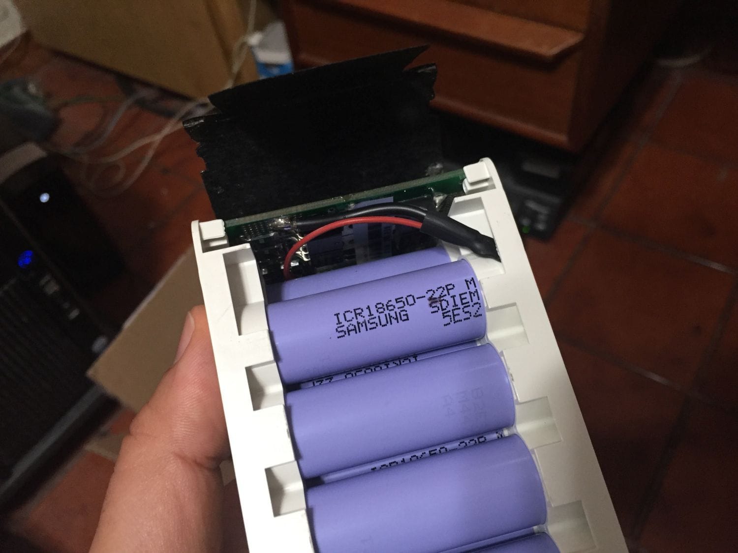
I checked the original battery pack - it's a 21 cell pack with Samsung ICR 18650's. Not that keen on the volatility of ICR's - will post some photos soon. In the meantime:
-Kurt
I checked the original battery pack - it's a 21 cell pack with Samsung ICR 18650's. Not that keen on the volatility of ICR's - will post some photos soon. In the meantime:
-Kurt
__________________
03-29-20, 06:31 PM
#24
Senior Member
Join Date: Jul 2014
Location: socal
Posts: 4,262
Mentioned: 9 Post(s)
Tagged: 0 Thread(s)
Quoted: 881 Post(s)
Liked 820 Times
in
620 Posts
Nice job; you became an ebike expert in one swoop. You should be able to hide the rat's nest in some kind of bag/box maybe attached to the rack, but leave the controller exposed to air to keep it from overheating.
Likes For 2old:
03-29-20, 08:01 PM
#25
www.theheadbadge.com
Thread Starter
Join Date: Sep 2005
Location: Southern Florida
Posts: 28,513
Bikes: https://www.theheadbadge.com
Mentioned: 124 Post(s)
Tagged: 0 Thread(s)
Quoted: 2422 Post(s)
Liked 4,390 Times
in
2,092 Posts
Wrapped half of the wiring in 12mm spiral wrap wire organizer. I'll do the remainder in 8mm. No messy cables around here, thank you.

And here's what it looks like now. It's nice to have a frame with internal cable routing...doesn't look much different than before. Stealth.

Rat's nest is mostly complete, except for the battery wires.
Here's the eBay battery with the shrinkwrap removed. 21 Samsung cells with the aforementioned ICR chemistry. Part number on the pack brought up nothing on Google, neither did the barcode, or the number on the PCB - or the PCB's part number itself. I don't think I'm going to use this. Plus, the so-called charger shipped with the battery is really a power supply

-Kurt
And here's what it looks like now. It's nice to have a frame with internal cable routing...doesn't look much different than before. Stealth.
Rat's nest is mostly complete, except for the battery wires.
Here's the eBay battery with the shrinkwrap removed. 21 Samsung cells with the aforementioned ICR chemistry. Part number on the pack brought up nothing on Google, neither did the barcode, or the number on the PCB - or the PCB's part number itself. I don't think I'm going to use this. Plus, the so-called charger shipped with the battery is really a power supply
-Kurt
__________________