


3D Printed Accessories / Mounts
 09-05-18, 11:17 AM
#476

Ride it like you stole it
Thread Starter

__________________
"Never use your face as a brake pad" - Jake Watson
The Reloutionaries @ Shapeways
"Never use your face as a brake pad" - Jake Watson
The Reloutionaries @ Shapeways
 09-06-18, 05:32 AM
#477
Senior Member
Join Date: May 2010
Posts: 745
Mentioned: 4 Post(s)
Tagged: 0 Thread(s)
Quoted: 188 Post(s)
Likes: 0
Liked 3 Times
in
3 Posts
@edthesped, great, I built one and have played with different springs etc. I also printed a second one out for my nephew, I don't think he has put it together yet. I have nothing to compare it to other than the Park tensiometer. It is very consistent in it's readings. Without a calibration chart I can only guess what the actual spoke tension is. I tested mine with a wheel I built that I knew was near perfect when it came to consistent spoke tension. Still it would be nice to see how it fair against some of the very high priced tensiometers this mimics. I think I built mine with mostly Chinese parts (slide, bearings and gauge) for under $30 plus about three hours of printing. I can't take any credit for the actual design, I found this on Thingiverse myself. I just had to remodel the parts to fit more readily available parts you could buy on Amazon.
I think it's easier to make a calibration jig than it is to make the tensiometer... I made my jig based off of the one in the following video and have found it works quite well. (The DT Swiss Tensiometer only provides charting for DT Swiss spokes) I compared my results from the tensiometer to those in the DT Swiss table and they're pretty much spot on so I have confidence in the Jig. (in my case I used wood rather than steel to make my frame)
This is the one I purchased only it was $25. when I purchased it a couple of years back.
Last edited by edthesped; 09-06-18 at 05:37 AM.
09-18-18, 07:57 AM
#478
Ride it like you stole it
Thread Starter
Since Trek cannot leave well enough alone, the new Madone SLR uses a different method to attach the rear derailleur compared to the Madone SL. I have an adapter for a Garmin Varia that uses the existing reflector amount. I also have a GoPro mount that replaces the reflector mount in total. Should be available soon.

Madone SLR GoPro Mount
Madone SLR GoPro Mount
__________________
"Never use your face as a brake pad" - Jake Watson
The Reloutionaries @ Shapeways
"Never use your face as a brake pad" - Jake Watson
The Reloutionaries @ Shapeways
09-23-18, 06:23 AM
#479
Ride it like you stole it
Thread Starter
Got a few images of the Trek Madone SLR Varia Adapter in use. This uses the supplied rear reflector mount and transforms it into a Garmin Varia mount.

Using this adapter does give you a bit of tilt adjustability.

The adapter itself.

Simply reuse the existing bolt and nut.

It does place the Varia centered on the Trek seat mast.
Using this adapter does give you a bit of tilt adjustability.
The adapter itself.
Simply reuse the existing bolt and nut.
It does place the Varia centered on the Trek seat mast.
__________________
"Never use your face as a brake pad" - Jake Watson
The Reloutionaries @ Shapeways
"Never use your face as a brake pad" - Jake Watson
The Reloutionaries @ Shapeways
10-22-18, 12:49 PM
#480
Ride it like you stole it
Thread Starter
More stuff for the Trek Madone SLR, Cyclig FLY6ce mount that works with the reflector bracket and a GoPro mount that replaces the reflector bracket. The bracket is Trek part number W557631.
__________________
"Never use your face as a brake pad" - Jake Watson
The Reloutionaries @ Shapeways
"Never use your face as a brake pad" - Jake Watson
The Reloutionaries @ Shapeways
11-07-18, 05:07 AM
#481
Ride it like you stole it
Thread Starter
If any of you 'designers' out there have any items you have modeled and want them before XMAS here are the last dates you may order them and still get them in time.
North America and EU:
Other Global:
Sculpteo has not yet communicated their cutoff dates, but note most of their plastics are printed in France.
North America and EU:
- December 6: Professional Plastic
- December 13: Versatile Plastic
Other Global:
- December 4: Professional Plastic
- December 11: Versatile Plastic
Sculpteo has not yet communicated their cutoff dates, but note most of their plastics are printed in France.
__________________
"Never use your face as a brake pad" - Jake Watson
The Reloutionaries @ Shapeways
"Never use your face as a brake pad" - Jake Watson
The Reloutionaries @ Shapeways
11-12-18, 05:16 PM
#482
Ride it like you stole it
Thread Starter
So I wasn't real happy with the first Spoke Tension Meter that I printed. It works and it works very well. Provides consistent readings, but it is a bit unwieldy in use. This is a different design that used less parts. I have released all the files necessary to print your own on Thingiverse using a Creative Commons license. The parts list is reduced from the previous design. In my testing it too is very consistent in readings. With a digital dial indicator it would also be much lighter. The Park Tools one in the picture is very heavy and was just leftover from another project.
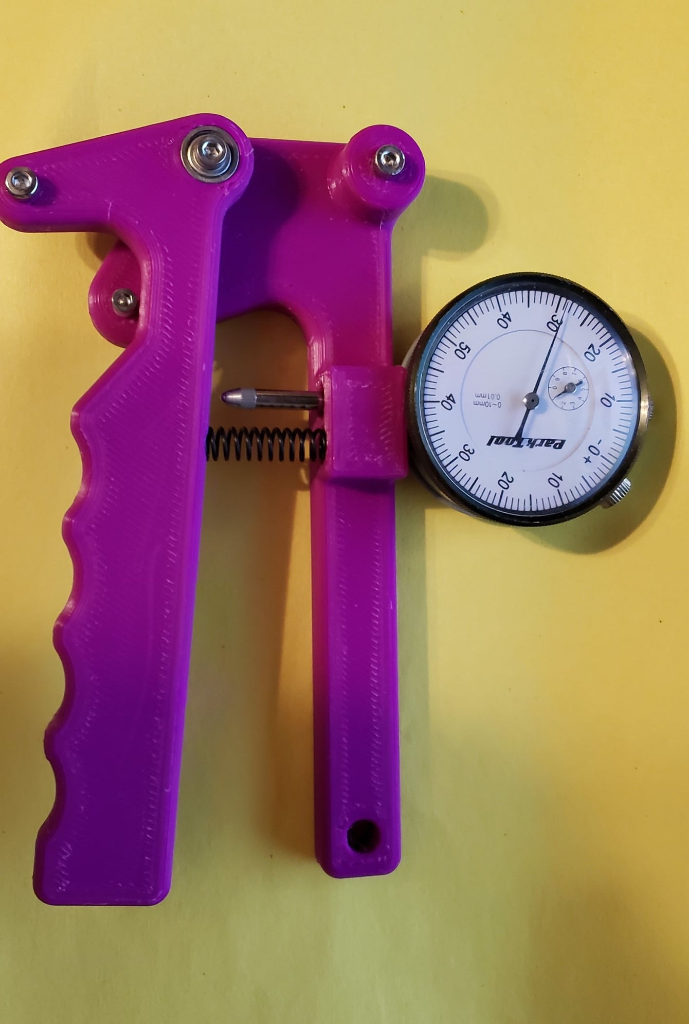
My printed Spoke Tension Meter

Top View

Home View
All the files, including 3D CAD files that can be imported into your favorite CAD application, are included at this link https://www.thingiverse.com/thing:3209607
Feel free to download, print and or modify it for your needs.
My printed Spoke Tension Meter
Top View
Home View
All the files, including 3D CAD files that can be imported into your favorite CAD application, are included at this link https://www.thingiverse.com/thing:3209607
Feel free to download, print and or modify it for your needs.
__________________
"Never use your face as a brake pad" - Jake Watson
The Reloutionaries @ Shapeways
"Never use your face as a brake pad" - Jake Watson
The Reloutionaries @ Shapeways
11-14-18, 10:21 AM
#483
Ride it like you stole it
Thread Starter
Spoke Tension Meter
Current version
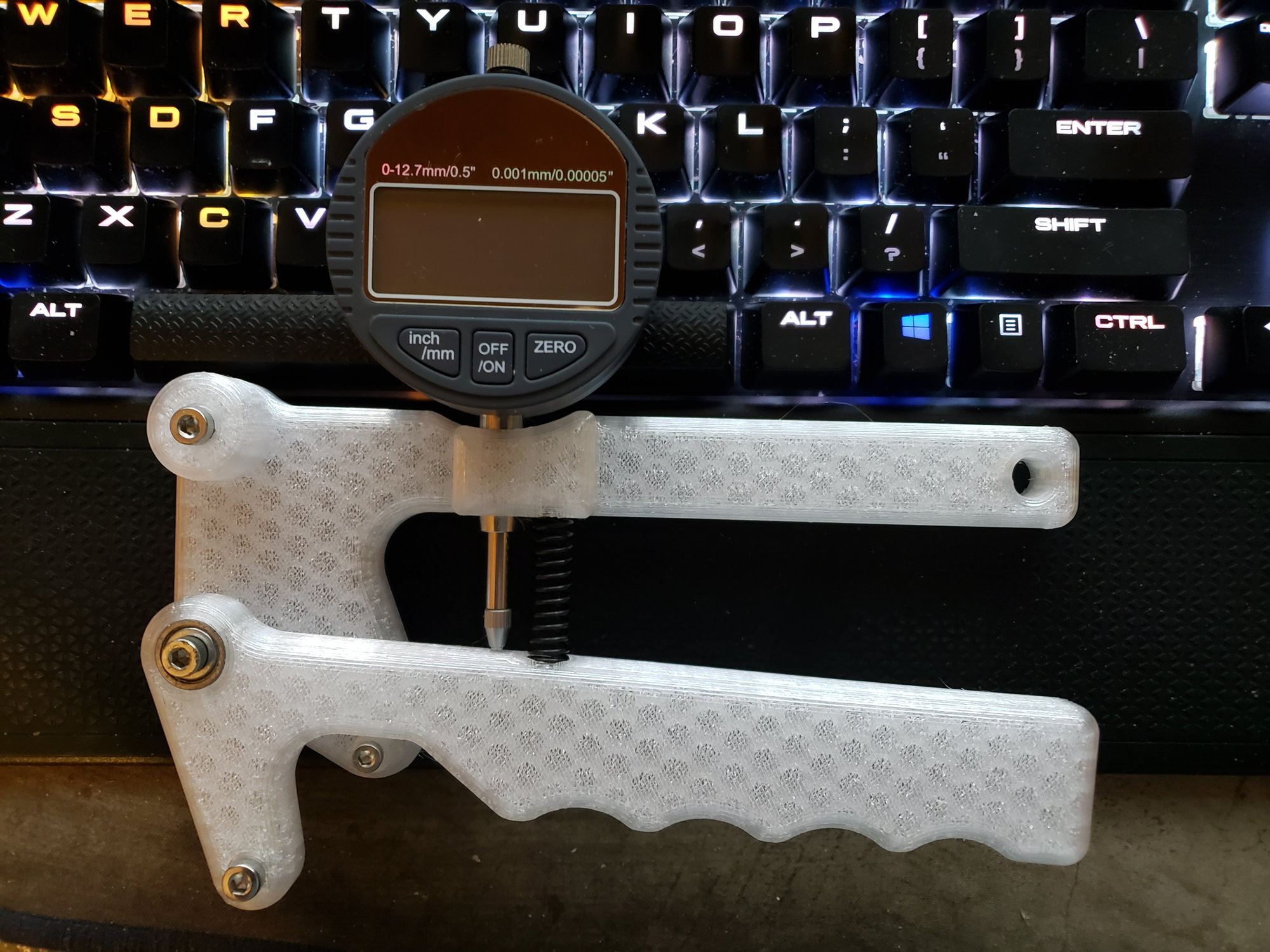
Update on spoke tension meter: I updated all the files yesterday after reprinting with PETG filament. There was a couple of small issues with the first version uploaded to Thingiverse, corrected now. On my Robo 3D R2 printer I have to instruct the slicer to adjust edges by -0.10 mm in order to get holes the correct size. Depending on your slicer settings you may need a similar size adjustment. The actual 3D model source file is correct to size. Current version is Version 5.
Here is a parts list:
- 2 - M4 x 20 mm socket head cap screws
- 1 - M4 x 12 mm socket head cap screw
- 3 - M4 nylon insert lock nut
- 1 - M3 x 12 mm socket head cap screw
- 1 - M3 nylon insert lock nut
- 1 - M2 x 10 mm socket head cap screw
- 1 - M2 nut (must not be a locking nut)
- 1 - 0.041" x 0.312" x 1.25" compression spring
- 1 - 12.7 mm (1/2") dial indicator ( I prefer digital for easier reading)
- 1 - 624zz precision bearing
- 1 - M4 nylon washer (sits between the two handle parts)
@edthesped, my next project is to build a spoke tension calibration fixture like you pointed to above, post #477.
__________________
"Never use your face as a brake pad" - Jake Watson
The Reloutionaries @ Shapeways
"Never use your face as a brake pad" - Jake Watson
The Reloutionaries @ Shapeways
Last edited by WheresWaldo; 11-14-18 at 10:30 AM.
11-14-18, 10:36 AM
#484

aka Tom Reingold

Join Date: Jan 2009
Location: New York, NY, and High Falls, NY, USA
Posts: 40,503
Bikes: 1962 Rudge Sports, 1971 Raleigh Super Course, 1971 Raleigh Pro Track, 1974 Raleigh International, 1975 Viscount Fixie, 1982 McLean, 1996 Lemond (Ti), 2002 Burley Zydeco tandem
Mentioned: 511 Post(s)
Tagged: 0 Thread(s)
Quoted: 7348 Post(s)
Liked 2,470 Times
in
1,435 Posts
@Dan Burkhart, have you seen this?
__________________
Tom Reingold, tom@noglider.com
New York City and High Falls, NY
Blogs: The Experienced Cyclist; noglider's ride blog
�When man invented the bicycle he reached the peak of his attainments.� � Elizabeth West, US author
Please email me rather than PM'ing me. Thanks.
Tom Reingold, tom@noglider.com
New York City and High Falls, NY
Blogs: The Experienced Cyclist; noglider's ride blog
�When man invented the bicycle he reached the peak of his attainments.� � Elizabeth West, US author
Please email me rather than PM'ing me. Thanks.
11-14-18, 11:05 AM
#485
Senior member

Join Date: Oct 2004
Location: Oakville Ontario
Posts: 8,117
Mentioned: 25 Post(s)
Tagged: 0 Thread(s)
Quoted: 943 Post(s)
Liked 658 Times
in
371 Posts
@Dan Burkhart, have you seen this?
11-14-18, 11:10 AM
#486
Ride it like you stole it
Thread Starter
@noglider and @Dan Burkhart
I think if you are going to print one of these for shop use, I would make sure you increase the infill. I printed mine with 3 perimeters and 4 layers on top and bottom, with only a 25% infill. It makes for a very lightweight version, especially if you are using a cheap Chinese digital dial indicator. I am not sure that for a tool like this you need to buy an expensive Japanese or US made dial indicator. Even buying everything from HomeDepot or Lowes and Harbor Freight (for dial Indicator with a 20% off coupon) you would be hard pressed to spend more than $30 on this tool in total.
I also included STEP and F3D files of the 3D source, specifically for people that want to modify the design in any way. STEP will import into most 3D CAD applications and F3D is a direct Autodesk Fusion 360 file.
Note: I printed mine with no supports, there aren't many sections with large overhangs (only the nut recesses) so bridging is very easy for most printers.
__________________
"Never use your face as a brake pad" - Jake Watson
The Reloutionaries @ Shapeways
"Never use your face as a brake pad" - Jake Watson
The Reloutionaries @ Shapeways
Last edited by WheresWaldo; 11-14-18 at 11:24 AM.
11-19-18, 11:18 AM
#487


Randomhead
Join Date: Aug 2008
Location: Happy Valley, Pennsylvania
Posts: 24,397
Mentioned: 0 Post(s)
Tagged: 0 Thread(s)
Quoted: 4 Post(s)
Liked 3,698 Times
in
2,518 Posts
I have a part that I'm going to get printed in plastic at shapeways. It is a brush holder, as in a carbon motor contact brush. So I want the brush to be able to slide in a square hole. If the brushes are 3.92mm, what size hole should I put in the part? I was thinking that I would design parts with different size holes, but it would be nice to know where to start. Probably get it printed in versatile plastic to start, and then professional plastic when I'm happy with the design.
11-22-18, 02:27 PM
#488
Ride it like you stole it
Thread Starter
@unterhausen my guess for your square hole would be to size it approximately to 3.97 mm, that is a bit less than 1/2 of Shapeways stated printing accuracy. Their formula is 0.15 mm + 0.15% of the longest axis. Anecdotally when dealing with rather small parts, like the ones I have designed, the accuracy appears greater but does have a tendency to run factionally smaller than true-to-life dimensions. As an example, my Garmin mount was modeled to be 31.20 mm in it's outside diameter and the finished print, regardless of print orientation, on average measures 31.15 mm. Another example, an M3 nut requires a polygon with an outside circumference of 5.5 mm, I typically model a recess for an M3 nut at 5.55 mm so that it does not require force to insert.
Please note that tolerances of Professional Plastic are a bit looser than Versatile Plastic, but also appear to run fractionally smaller than modeled and tighter than the specification on small models..
Please note that tolerances of Professional Plastic are a bit looser than Versatile Plastic, but also appear to run fractionally smaller than modeled and tighter than the specification on small models..
__________________
"Never use your face as a brake pad" - Jake Watson
The Reloutionaries @ Shapeways
"Never use your face as a brake pad" - Jake Watson
The Reloutionaries @ Shapeways
Last edited by WheresWaldo; 11-22-18 at 02:36 PM.
11-22-18, 02:32 PM
#489
Ride it like you stole it
Thread Starter
@noglider & @Dan Burkhart
There is a very small discussion group talking about tensiometer designs for 3D printing on Thingiverse;
Wheelbuilding Tensiometer (develoopment) (sic)
Spoke Tensiometer Calibration Rig (Ideas / Projects)
BTW, the current version of the DT Swiss Clone is Version 6, all files on Thingiverse were updated. I am also working on a 3D model of Mr. Burkhart's calibration rig, but since I can't weld, it is using 20x20 aluminum V-slot extrusion for the frame. It too will be posted on Thingiverse with a complete parts list, when it is ready.
__________________
"Never use your face as a brake pad" - Jake Watson
The Reloutionaries @ Shapeways
"Never use your face as a brake pad" - Jake Watson
The Reloutionaries @ Shapeways
Last edited by WheresWaldo; 11-22-18 at 02:38 PM.
11-22-18, 05:27 PM
#490
Senior member
Join Date: Oct 2004
Location: Oakville Ontario
Posts: 8,117
Mentioned: 25 Post(s)
Tagged: 0 Thread(s)
Quoted: 943 Post(s)
Liked 658 Times
in
371 Posts
@noglider & @Dan Burkhart
There is a very small discussion group talking about tensiometer designs for 3D printing on Thingiverse;
Wheelbuilding Tensiometer (develoopment) (sic)
Spoke Tensiometer Calibration Rig (Ideas / Projects)
BTW, the current version of the DT Swiss Clone is Version 6, all files on Thingiverse were updated. I am also working on a 3D model of Mr. Burkhart's calibration rig, but since I can't weld, it is using 20x20 aluminum V-slot extrusion for the frame. It too will be posted on Thingiverse with a complete parts list, when it is ready.
There is a very small discussion group talking about tensiometer designs for 3D printing on Thingiverse;
Wheelbuilding Tensiometer (develoopment) (sic)
Spoke Tensiometer Calibration Rig (Ideas / Projects)
BTW, the current version of the DT Swiss Clone is Version 6, all files on Thingiverse were updated. I am also working on a 3D model of Mr. Burkhart's calibration rig, but since I can't weld, it is using 20x20 aluminum V-slot extrusion for the frame. It too will be posted on Thingiverse with a complete parts list, when it is ready.
Here is the updates I did on it. The video is a bit tongue in cheek, assigning model numbers and such.
11-23-18, 11:55 AM
#491
Randomhead
Join Date: Aug 2008
Location: Happy Valley, Pennsylvania
Posts: 24,397
Mentioned: 0 Post(s)
Tagged: 0 Thread(s)
Quoted: 4 Post(s)
Liked 3,698 Times
in
2,518 Posts
I like that calibrator. I really want to make a one-sided design without a frame. I have thought about making one that always uses the same spoke, but I am sure my lbs owner will want one that will take various spokes.
11-23-18, 06:01 PM
#492
Senior member
Join Date: Oct 2004
Location: Oakville Ontario
Posts: 8,117
Mentioned: 25 Post(s)
Tagged: 0 Thread(s)
Quoted: 943 Post(s)
Liked 658 Times
in
371 Posts
The calibration fixture was indispensable to me when I began building a branded line of wheels with CXRay spokes for a LBS. My tension meter was not calibrated for those from the factory, and guessing would have put me way off. Tension readings on those are not even close to what you get with round spokes of any gauge.
11-26-18, 01:10 PM
#493
Ride it like you stole it
Thread Starter
Calibration device
Shapeways is offering 15% off sitewide for today and Tuesday, use the code HAPPYMONDAY
@unterhausen & @Dan Burkhart
I have been working on a calibration device. Dan, I appreciated the video links and came up with a few ideas on how to build one that 1. requires no welding; 2. can be assembled with mostly hand tools, a drill press and a single tap will be required in addition to normal hand tools; 3. provides consistent results. One thing I noticed, a lot of people that have built calibration devices might have published a picture or to, there are even a few posts here on BikeForums. No one has a list of parts nor do they have instructions on how to assemble one. Here is an image of what I am working on.

I am planning on including a complete parts list. I have only found a couple for sale online, and they were both over $500 USD. I think this one can be built as is for under $200, if you have to start from $0. A cheaper version that uses a smaller capacity crane scale and smaller extrusion could probably be built for under $100 USD. Of course those estimates are based on sourcing from China or eBay. There are a few 3D printed parts. I had to source a lot from China (AliExpress Black Friday sales) so I won't have built the first one until nearly the end of the year. I have no intention of making these for sale, I just want to supply the 3D design. I do have the design that is simpler than this one nearly done.
If you or the admins feel something like this should be posted in another forum, please feel free to copy/move this message as appropriate.
@unterhausen & @Dan Burkhart
I have been working on a calibration device. Dan, I appreciated the video links and came up with a few ideas on how to build one that 1. requires no welding; 2. can be assembled with mostly hand tools, a drill press and a single tap will be required in addition to normal hand tools; 3. provides consistent results. One thing I noticed, a lot of people that have built calibration devices might have published a picture or to, there are even a few posts here on BikeForums. No one has a list of parts nor do they have instructions on how to assemble one. Here is an image of what I am working on.
I am planning on including a complete parts list. I have only found a couple for sale online, and they were both over $500 USD. I think this one can be built as is for under $200, if you have to start from $0. A cheaper version that uses a smaller capacity crane scale and smaller extrusion could probably be built for under $100 USD. Of course those estimates are based on sourcing from China or eBay. There are a few 3D printed parts. I had to source a lot from China (AliExpress Black Friday sales) so I won't have built the first one until nearly the end of the year. I have no intention of making these for sale, I just want to supply the 3D design. I do have the design that is simpler than this one nearly done.
If you or the admins feel something like this should be posted in another forum, please feel free to copy/move this message as appropriate.
__________________
"Never use your face as a brake pad" - Jake Watson
The Reloutionaries @ Shapeways
"Never use your face as a brake pad" - Jake Watson
The Reloutionaries @ Shapeways
Last edited by WheresWaldo; 11-26-18 at 01:38 PM.
11-26-18, 01:27 PM
#494
Senior member
Join Date: Oct 2004
Location: Oakville Ontario
Posts: 8,117
Mentioned: 25 Post(s)
Tagged: 0 Thread(s)
Quoted: 943 Post(s)
Liked 658 Times
in
371 Posts
Shapeways is offering 15% off sitewide for today and Tuesday, use the code HAPPYMONDAY
@unterhausen & @Dan Burkhart
I have been working on a calibration device. Dan, I appreciated the video links and came up with a few ideas on how to build one that 1. requires no welding; 2. can be assembled with mostly hand tools, a drill press and a single tap will be required in addition to normal hand tools; 3. provides consistent results. One thing I noticed, a lot of people that have built calibration devices might have published a picture or to, there are even a few posts here on BikeForums. No one has a list of parts nor do they have instructions on how to assemble one. Here is an image of what I am working on.
I am planning on including a complete parts list. I have only found a couple for sale online, and they were both of $500 USD. I think this one can be built as is for under $200, if you have to start from $0. A cheaper version that uses a smaller capacity crane scale and smaller extrusion could probably be built for under $100 USD. Of course those estimates are based on sourcing from China or eBay. There are a few 3D printed parts. I had to source a lot from China (AliExpress Black Friday sales) so I won't have built the first one until nearing the end of the year. I have no intention of making these for sale, I just want to supply the 3D design. I do have the design that is simpler than this one nearly done.
If you or the admins feel something like this should be posted in another forum, please feel free to copy/move this message as appropriate.
 11-26-18, 04:16 PM
#495
Newbie
Join Date: Nov 2018
Posts: 1
Mentioned: 1 Post(s)
Tagged: 0 Thread(s)
Quoted: 0 Post(s)
Likes: 0
Liked 0 Times
in
0 Posts
Hello, my first post here. I need a mount for a rear varia RTL 510 for a Cannondale synapse with 25,4 rear post. How can I look for it?. Thanks a lot.
11-27-18, 12:38 PM
#496
Ride it like you stole it
Thread Starter
@Kroter, here is a link - https://shpws.me/MuBU
If you order anything from Shapeways, they are offering 15% off sitewide (HAPPYMONDAY). Today is the last day.
If you order anything from Shapeways, they are offering 15% off sitewide (HAPPYMONDAY). Today is the last day.
__________________
"Never use your face as a brake pad" - Jake Watson
The Reloutionaries @ Shapeways
"Never use your face as a brake pad" - Jake Watson
The Reloutionaries @ Shapeways
12-16-18, 07:15 PM
#497
Senior Member
Join Date: May 2010
Posts: 745
Mentioned: 4 Post(s)
Tagged: 0 Thread(s)
Quoted: 188 Post(s)
Likes: 0
Liked 3 Times
in
3 Posts
Current version
Update on spoke tension meter: I updated all the files yesterday after reprinting with PETG filament. There was a couple of small issues with the first version uploaded to Thingiverse, corrected now. On my Robo 3D R2 printer I have to instruct the slicer to adjust edges by -0.10 mm in order to get holes the correct size. Depending on your slicer settings you may need a similar size adjustment. The actual 3D model source file is correct to size. Current version is Version 5.
Here is a parts list:
- 2 - M4 x 20 mm socket head cap screws
- 1 - M4 x 12 mm socket head cap screw
- 3 - M4 nylon insert lock nut
- 1 - M3 x 12 mm socket head cap screw
- 1 - M3 nylon insert lock nut
- 1 - M2 x 10 mm socket head cap screw
- 1 - M2 nut (must not be a locking nut)
- 1 - 0.041" x 0.312" x 1.25" compression spring
- 1 - 12.7 mm (1/2") dial indicator ( I prefer digital for easier reading)
- 1 - 624zz precision bearing
- 1 - M4 nylon washer (sits between the two handle parts)
@edthesped, my next project is to build a spoke tension calibration fixture like you pointed to above, post #477.
Really sweet design!!!
12-17-18, 06:59 AM
#498
Ride it like you stole it
Thread Starter
@edthesped,
I have the design for two versions of the calibration rig nearly completed. They are basically buildable with off the shelf parts. There are four parts that require a drill press and two of those require a tap to cut threads for the spoke holders. The smaller, cheaper version does not require the tap. When I have one built, I will post a complete parts list. I have most of the parts already with the rest on the way. I am pretty sure it is a sound design, but of course until one is actually built I cannot be 100% certain.
Oh and I changed one part on the tensiometer, the M2 x 10 and M2 nut where changed to M3 for the latest version up on Thingiverse.
__________________
"Never use your face as a brake pad" - Jake Watson
The Reloutionaries @ Shapeways
"Never use your face as a brake pad" - Jake Watson
The Reloutionaries @ Shapeways
12-27-18, 07:33 AM
#499
Ride it like you stole it
Thread Starter
Tensiometer calibration rig
I am almost done with my first model of the calibration rig for tensiometers. It isn't a ZwickRoell but then again, if you bought every part and bolt from owning nothing, this one should run about $80 USD in parts. After I test it I will post a complete parts list. It should do the job it is intended for. Here is a peek of what it looks like:

I have only pictured the top section because that is all that is complete while I am waiting on a few parts. With the pictured crane scale it can measure up to 1471 newtons (150 kg x 9.80665) [or as Park Tools will state 1500 newtons as they use an incorrect formula of how to calculate a newton].
My pricing estimate is buying all parts from US online retailers not direct from China. Places like McMaster-Carr and Amazon. There are a few 3D printed parts and you need a drill press or a very steady hand to drill the required 5 holes. This version also doesn't need a tap. I did need to use my Dremel tool to sand down a couple of parts. It is assembled with only hand tools.
__________________
"Never use your face as a brake pad" - Jake Watson
The Reloutionaries @ Shapeways
"Never use your face as a brake pad" - Jake Watson
The Reloutionaries @ Shapeways
Last edited by WheresWaldo; 12-27-18 at 07:41 AM.
12-27-18, 11:43 AM
#500
Ride it like you stole it
Thread Starter
Calibration device
I have gotten much further along and have a working version of the Spoke Tensiometer Calibration Rig. It is still missing a part (Thrust Bearing) and there are a couple of things I would change but here it is:

In the picture above the spoke is being pulled with 102.7 kg so the spoke tension is 1000 newtons. I double checked my Park Tool TM-1 chart together with my rarely used TM-1 and it was close. The TM-1 was one marking too low with a 1.8 mm spoke. So here is the parts list.
This list will build the model with the items I would do differently. The difference is that the pictured version uses an M6 Threaded Rod and that should change to an M8 or M10. It is not a strength issue, it is a space issue. Besides this you need a few drill bits and a way to drill straight holes. Some Allen Head Hex Wrenches and some time to print the 3D parts and putting it all together. Total cost building this was under $80 USD.
If someone wants to post this in the mechanics forum please feel free to do so.
In the picture above the spoke is being pulled with 102.7 kg so the spoke tension is 1000 newtons. I double checked my Park Tool TM-1 chart together with my rarely used TM-1 and it was close. The TM-1 was one marking too low with a 1.8 mm spoke. So here is the parts list.
- 2 - 2020 Series x 500 mm T-Slot
- 4 - 2020 Series Corners (or 3D printed equivalents)
- 8 - M5 x 10 mm Button Head Screws
- 8 - M5 T-Slot Nuts
- 1 - M8 x 35 mm Button Head Screw
- 1 - M8 Washer
- 1 - M8 Flat Thumbscrew
- 1 - M8 x 200 mm Threaded Rod
- 1 - M8 Hex Bolt
- 2 - M8 Acorn Nuts
- 1 - 8 mm Roller Thrust Bearing
- 2 - M8 Clevis Rod Ends
- Small Crane Scale (150 kg or more capacity)
- 1 - Brass Spoke Nipple
- Some 3D Printed Parts
This list will build the model with the items I would do differently. The difference is that the pictured version uses an M6 Threaded Rod and that should change to an M8 or M10. It is not a strength issue, it is a space issue. Besides this you need a few drill bits and a way to drill straight holes. Some Allen Head Hex Wrenches and some time to print the 3D parts and putting it all together. Total cost building this was under $80 USD.
If someone wants to post this in the mechanics forum please feel free to do so.
__________________
"Never use your face as a brake pad" - Jake Watson
The Reloutionaries @ Shapeways
"Never use your face as a brake pad" - Jake Watson
The Reloutionaries @ Shapeways
Last edited by WheresWaldo; 12-28-18 at 11:49 AM.