


Cold set not happening
 01-29-21, 10:46 AM
#1

Senior Member
Thread Starter
Join Date: Aug 2007
Location: Evanston, IL
Posts: 5,093
Bikes: many
Mentioned: 63 Post(s)
Tagged: 0 Thread(s)
Quoted: 1444 Post(s)
Liked 1,392 Times
in
760 Posts
Cold set not happening
I'm trying to cold set an early 80s Schwinn Super Sport from 120mm to 126mm rear spacing. This is the second frame frame I've cold set. The first was a mid-80s Conti which was easy peasy. Spread the spacing to about 144mm with threaded rod and nuts and it relaxed back just about where I intended at 126. I tried the same technique on the Super Sport, so far with no luck. I used the same threaded rod/nuts/washers to open the spacing to 144mm and let it sit for a couple days. Here's what my setup looked like. It's not real obvious from the angle of the shot, but the threaded rod has a couple fender washers inboard of each dropout and nuts inside of them. I just crank them out until I reach the desired distance, tap in the board and clamp it to the rod (to keep it from going anywhere), make sure the clamps on the stays are nice and snug, then go do something else for a day or two.

I'm skeptical the clamps ahead of the two bridges had any real effect, but they made me feel better. The board tapped in between the chain stays was to encourage some of the bending to happen a bit further forward. Also probably unnecessary.
After two days, I undid everything and measured. It relaxed back to 121mm. Hmmm... I went a bit further, to 146mm, and let it sit another day. Still 121mm after that. Finally, yesterday, I widened the nuts to take the spacing to 152mm. Checking this morning, I found it relaxed back to 121mm again. I have clearly so far not exceeded the elastic limit of the stays.
The sticker on the seat tube says it's Tange Champion No 2, which I think is pretty generic 4130 steel, not hardened, correct? I'm guessing the chain stays (and seat stays?) are just really stout. How am I going to get this rear triangle spread to 126mm without breaking the brazed joints at the brake bridge or chain stay bridge? Are my clamps improving the chances that when the stays finally move that those joints remain intact, or am I just fooling myself?
 01-29-21, 11:55 AM
#2
Senior Member
Join Date: Dec 2019
Posts: 955
Mentioned: 3 Post(s)
Tagged: 0 Thread(s)
Quoted: 321 Post(s)
Liked 263 Times
in
212 Posts
You don't need to leave it for a few days or a day or any time at all. Steel doesn't "creep". It will spring back to whatever it's gonna spring back to right away.
It may be just that these stays are a bit stiffer than the other ones you tried. So just need to go a bit further. If it moved 1mm then you're in the ball park.
Keep going 10mm at a time. So 150, then try 160, etc. Or 5mm increments if you like. Crank it out then crank it straight back right away and measure it. Wear safety glasses. If you get freaked out then stop a bit short. You can just squeeze the wheel in anyway. I doubt the bridge tubes will pop out as they're quite far away. The stays should bend first.
A top tip from Paul Brodie's videos is actually to go 1mm more than you need. This makes it easier to get the wheel in. It really works. So in that case you'd go to 127.
Last edited by guy153; 01-29-21 at 11:59 AM.
01-29-21, 12:22 PM
#3
Senior Member
Join Date: Feb 2012
Location: Rochester, NY
Posts: 18,073
Bikes: Stewart S&S coupled sport tourer, Stewart Sunday light, Stewart Commuting, Stewart Touring, Co Motion Tandem, Stewart 3-Spd, Stewart Track, Fuji Finest, Mongoose Tomac ATB, GT Bravado ATB, JCP Folder, Stewart 650B ATB
Mentioned: 0 Post(s)
Tagged: 0 Thread(s)
Quoted: 4201 Post(s)
Liked 3,857 Times
in
2,305 Posts
You don't need to leave it for a few days or a day or any time at all. Steel doesn't "creep". It will spring back to whatever it's gonna spring back to right away.
It may be just that these stays are a bit stiffer than the other ones you tried. So just need to go a bit further. If it moved 1mm then you're in the ball park.
Keep going 10mm at a time. So 150, then try 160, etc. Or 5mm increments if you like. Crank it out then crank it straight back right away and measure it. Wear safety glasses. If you get freaked out then stop a bit short. You can just squeeze the wheel in anyway. I doubt the bridge tubes will pop out as they're quite far away. The stays should bend first.
A top tip from Paul Brodie's videos is actually to go 1mm more than you need. This makes it easier to get the wheel in. It really works. So in that case you'd go to 127.
It may be just that these stays are a bit stiffer than the other ones you tried. So just need to go a bit further. If it moved 1mm then you're in the ball park.
Keep going 10mm at a time. So 150, then try 160, etc. Or 5mm increments if you like. Crank it out then crank it straight back right away and measure it. Wear safety glasses. If you get freaked out then stop a bit short. You can just squeeze the wheel in anyway. I doubt the bridge tubes will pop out as they're quite far away. The stays should bend first.
A top tip from Paul Brodie's videos is actually to go 1mm more than you need. This makes it easier to get the wheel in. It really works. So in that case you'd go to 127.
I pretty much agree with a comment or three.
The board is doing nothing to where or how the stays bend, it's on the wrong side of the stays to do that.
The OP stated he was aiming for 126. What we don't know (and it seems that there's always missing data in these types of posts) is what the "new" wheel is, axle width wise.
The OP seems to be assuming that both stays will bend symmetrically. Often they don't because of reasons like drive side chain stays can have different indents for chain ring clearance that the LH side doesn't. This is the main reason why I do my rear triangle spreading one side at a time. I block the BB shell (what, you mean I have to do more work just to realign a frame...) in a bench vise and work on one set of stays, then the other. Besides controlling where you end more easily you also do a better job at maintaining the frame's chain line and tracking.
That there's so much spring back speaks to both the material grade as well as the construction quality (as in not being cooked during brazing).
If the OP wants to promote the bending behind/below the bridges those pipe clamps should be placed below/behind the bridges, not on top of them. Andy
__________________
AndrewRStewart
AndrewRStewart
Likes For Andrew R Stewart:
01-29-21, 12:35 PM
#4
Full Member
I pretty much agree with a comment or three.
The OP seems to be assuming that both stays will bend symmetrically. Often they don't because of reasons like drive side chain stays can have different indents for chain ring clearance that the LH side doesn't. This is the main reason why I do my rear triangle spreading one side at a time. I block the BB shell (what, you mean I have to do more work just to realign a frame...) in a bench vise and work on one set of stays, then the other. Besides controlling where you end more easily you also do a better job at maintaining the frame's chain line and tracking.
The OP seems to be assuming that both stays will bend symmetrically. Often they don't because of reasons like drive side chain stays can have different indents for chain ring clearance that the LH side doesn't. This is the main reason why I do my rear triangle spreading one side at a time. I block the BB shell (what, you mean I have to do more work just to realign a frame...) in a bench vise and work on one set of stays, then the other. Besides controlling where you end more easily you also do a better job at maintaining the frame's chain line and tracking.
01-29-21, 01:01 PM
#5
Senior Member
Thread Starter
Join Date: Aug 2007
Location: Evanston, IL
Posts: 5,093
Bikes: many
Mentioned: 63 Post(s)
Tagged: 0 Thread(s)
Quoted: 1444 Post(s)
Liked 1,392 Times
in
760 Posts
Thanks for the replies. I don't expect the stays to necessarily move the same amount, but they should be closer to equidistant from the centerline if I spread them together rather than using the Sheldon Brown 2x4 method. I use a 4-foot level between the dropouts and the head tube to measure the distance from the seat tube (the string method with a "better" string). That will be good enough for me. As for the clamp on the seat stays, they contact the stays below the bridge. Their faces are parallel to one another while the stays form more of a Λ shape. (Also, that pic was taken on my first try a few days ago, so may not reflect "refinements" in positioning.)
I'll try the 5mm increment thing. I'm happy nobody said, "That won't work. Your tubing is heat treated."
I'll try the 5mm increment thing. I'm happy nobody said, "That won't work. Your tubing is heat treated."
01-29-21, 01:14 PM
#6
Senior Member
Join Date: Feb 2012
Location: Rochester, NY
Posts: 18,073
Bikes: Stewart S&S coupled sport tourer, Stewart Sunday light, Stewart Commuting, Stewart Touring, Co Motion Tandem, Stewart 3-Spd, Stewart Track, Fuji Finest, Mongoose Tomac ATB, GT Bravado ATB, JCP Folder, Stewart 650B ATB
Mentioned: 0 Post(s)
Tagged: 0 Thread(s)
Quoted: 4201 Post(s)
Liked 3,857 Times
in
2,305 Posts
Thanks for the replies. I don't expect the stays to necessarily move the same amount, but they should be closer to equidistant from the centerline if I spread them together rather than using the Sheldon Brown 2x4 method. I use a 4-foot level between the dropouts and the head tube to measure the distance from the seat tube (the string method with a "better" string). That will be good enough for me. As for the clamp on the seat stays, they contact the stays below the bridge. Their faces are parallel to one another while the stays form more of a Λ shape. (Also, that pic was taken on my first try a few days ago, so may not reflect "refinements" in positioning.)
I'll try the 5mm increment thing. I'm happy nobody said, "That won't work. Your tubing is heat treated."
I'll try the 5mm increment thing. I'm happy nobody said, "That won't work. Your tubing is heat treated."
I'll quibble with the heat treated comment. To my knowledge all bike tubing (and all steel production) uses heating steps at different points along the process. The bike industry use of the term "heat treated" is an attempt to use engineering terms for marketing purposes. All "heat treated" tubing is is just the continuing use of thermal treatment to further affect the strength of the tube beyond the other offerings that company also makes. Andy (who does know what you meant, but feeling a bit randy today though)
__________________
AndrewRStewart
AndrewRStewart
01-29-21, 01:36 PM
#7
Senior Member
Join Date: Dec 2019
Posts: 955
Mentioned: 3 Post(s)
Tagged: 0 Thread(s)
Quoted: 321 Post(s)
Liked 263 Times
in
212 Posts
The OP seems to be assuming that both stays will bend symmetrically. Often they don't because of reasons like drive side chain stays can have different indents for chain ring clearance that the LH side doesn't. This is the main reason why I do my rear triangle spreading one side at a time. I block the BB shell (what, you mean I have to do more work just to realign a frame...) in a bench vise and work on one set of stays, then the other. Besides controlling where you end more easily you also do a better job at maintaining the frame's chain line and tracking.
In any case OP should rig up a bit of string and keep an eye on things. Maybe the frame wasn't perfectly aligned to start with and this might be an opportunity to correct it.
01-29-21, 01:43 PM
#8
Senior Member
Join Date: Dec 2019
Posts: 955
Mentioned: 3 Post(s)
Tagged: 0 Thread(s)
Quoted: 321 Post(s)
Liked 263 Times
in
212 Posts
Thanks for the replies. I don't expect the stays to necessarily move the same amount, but they should be closer to equidistant from the centerline if I spread them together rather than using the Sheldon Brown 2x4 method. I use a 4-foot level between the dropouts and the head tube to measure the distance from the seat tube (the string method with a "better" string). That will be good enough for me. As for the clamp on the seat stays, they contact the stays below the bridge. Their faces are parallel to one another while the stays form more of a Λ shape. (Also, that pic was taken on my first try a few days ago, so may not reflect "refinements" in positioning.)
I'll try the 5mm increment thing. I'm happy nobody said, "That won't work. Your tubing is heat treated."
I'll try the 5mm increment thing. I'm happy nobody said, "That won't work. Your tubing is heat treated."
01-29-21, 01:47 PM
#9


Randomhead
Join Date: Aug 2008
Location: Happy Valley, Pennsylvania
Posts: 24,396
Mentioned: 0 Post(s)
Tagged: 0 Thread(s)
Quoted: 4 Post(s)
Liked 3,696 Times
in
2,517 Posts
If the frame has weak stay brazing, the clamps would keep it from failing.
I have used the step on one dropout and pull on the other technique, which is probably a little more controllable than using allthread. But it would be harder to do with an inexpensive bike with thicker tubing. I prefer using a lever and a bb post though.
I have used the step on one dropout and pull on the other technique, which is probably a little more controllable than using allthread. But it would be harder to do with an inexpensive bike with thicker tubing. I prefer using a lever and a bb post though.
01-29-21, 02:04 PM
#10
Senior Member
Join Date: Dec 2019
Posts: 955
Mentioned: 3 Post(s)
Tagged: 0 Thread(s)
Quoted: 321 Post(s)
Liked 263 Times
in
212 Posts
I'll quibble with the heat treated comment. To my knowledge all bike tubing (and all steel production) uses heating steps at different points along the process. The bike industry use of the term "heat treated" is an attempt to use engineering terms for marketing purposes. All "heat treated" tubing is is just the continuing use of thermal treatment to further affect the strength of the tube beyond the other offerings that company also makes. Andy (who does know what you meant, but feeling a bit randy today though)
Then it goes to the Reynolds factory (or equivalent) as seamless or DOM tube where they have a butting machine (about the size of a lathe), a hacksaw and an oven. They cut the tube and draw it a bit thinner (going from about 1mm to 0.8/0.5 or so) and butt it. This all happens cold. Then if it's a "heat-treated" tube (like 725 or 853, but Tange and others do this kind of thing as well) they cook it an oven in a special way that makes it stronger but less ductile. The hardness goes up from about 200 VPN to 400.
Tubes that are heat-treated like that are harder to dimple and bend and jack around with and this is a reason to prefer the non-heat-treated versions of the same tubes for the rear triangle.
01-30-21, 04:10 PM
#11
Senior Member
Thread Starter
Join Date: Aug 2007
Location: Evanston, IL
Posts: 5,093
Bikes: many
Mentioned: 63 Post(s)
Tagged: 0 Thread(s)
Quoted: 1444 Post(s)
Liked 1,392 Times
in
760 Posts
Again, thanks for the various inputs. I put on my cheapo safety glasses and got to work. I had to spread the dropouts to about 170mm with the threaded rod before they relaxed to something more than 121mm. I stopped at 124mm. The difference between the two sides measured at the seat tube is about 1-2mm. Close enough for government work. When the weather gets a bit nicer (in the spring?) I will finish things off outside with some gentle nudges using a 2x4. My shop is too small, my vice is not conveniently placed to do this indoors, and I didn't want to disassemble the crank/bb for this exercise (see: shipwright's disease). I will also refer back to some of the online instructions for creating a DIY dropout alignment tool. That I can tackle during the winter.
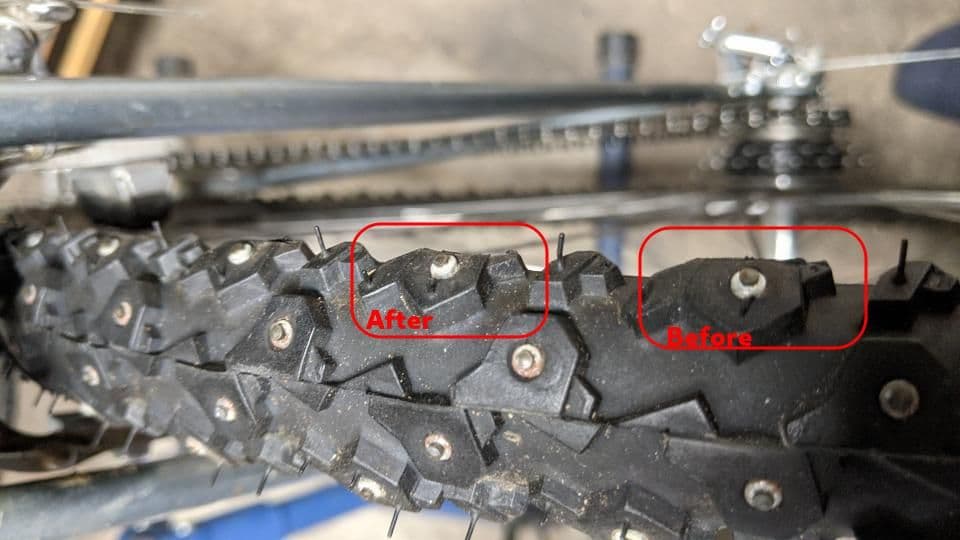
After that exercise I was able to easily mount the wheel. Alas, the (Nokian W240) tire was a touch too wide. No problem, just shave off the big knobs with a razor blade. Took off at most a mm per side. The tire just squeezes into the space with the dropout screws removed and the wheel all the way back in the dropouts. This exercise was easy to justify as the tires were freebies. I had initially thought I would just spring for some 45NRTH Xerxes which I knew would fit. This gets me on the road (and ice) without further cost or delay.
After that exercise I was able to easily mount the wheel. Alas, the (Nokian W240) tire was a touch too wide. No problem, just shave off the big knobs with a razor blade. Took off at most a mm per side. The tire just squeezes into the space with the dropout screws removed and the wheel all the way back in the dropouts. This exercise was easy to justify as the tires were freebies.
I had initially thought I would just spring for some 45NRTH Xerxes which I knew would fit. This gets me on the road (and ice) without further cost or delay.
Likes For smontanaro:
01-30-21, 04:17 PM
#12
Member
Join Date: Apr 2020
Location: Seattle
Posts: 36
Bikes: 2008 Rodriguez Adventure, 1995 TiCycles, 1995 KHS Montana Pro Custom, 2012 Surly Troll, 1976 Azuki Gran Sport Custom Frankenbike, 1974 Schwinn Sports Tourer, 1976 Schwinn Superior, 1989 Kona Cinder Cone
Mentioned: 1 Post(s)
Tagged: 0 Thread(s)
Quoted: 17 Post(s)
Liked 54 Times
in
16 Posts
Champion No. 2
I had an old Cenrurion Le Mans RS that was extremely difficult to cold set (going from 126mm to 130mm) but you just gotta keep at it. Basically Tange 2 is a Japanese 4130; stiff and very tough. Likes to spring back.
01-30-21, 05:55 PM
#13
framebuilder
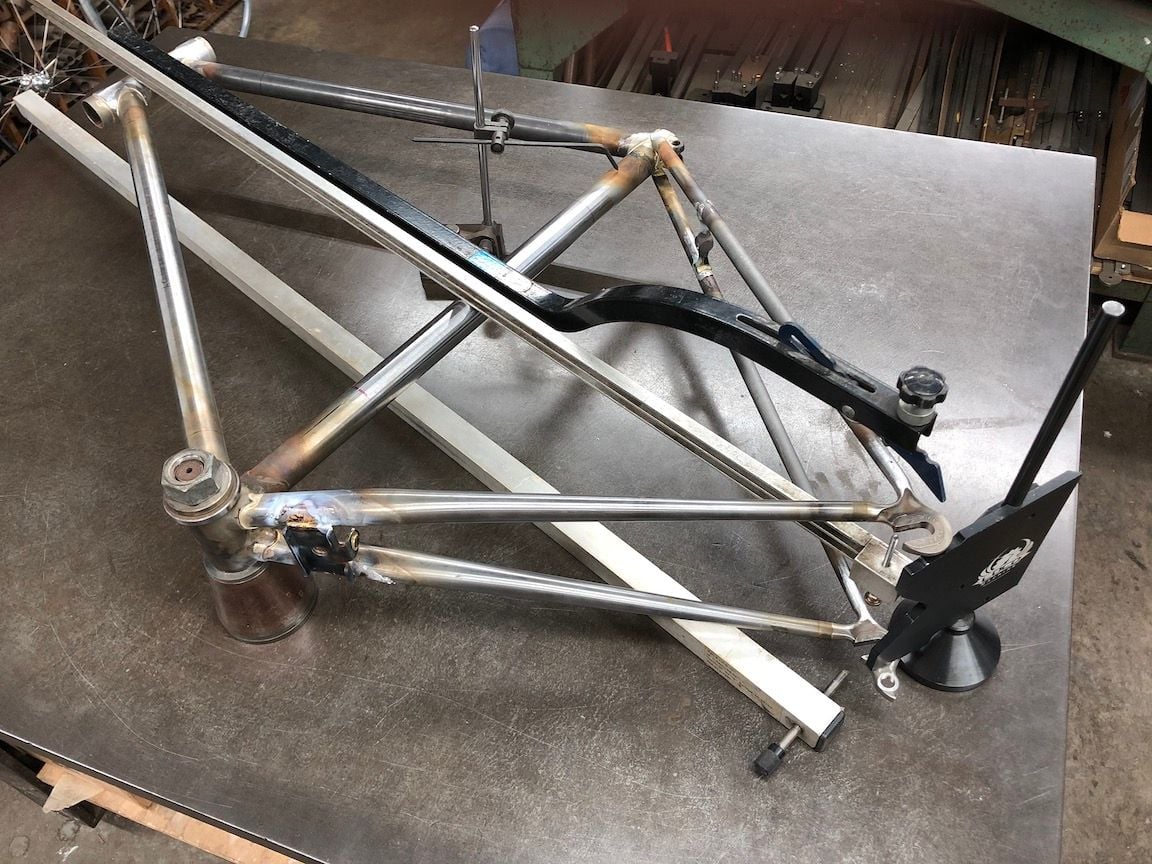
I've aligned thousands of frames in the 45 years I've had this cast iron table. It came from Johnny Berry's shop in Manchester and I suppose he got it from army surplus after the war. However there were a lot of British builders that didn't have an alignment table but what they all had was some kind of long straight edge with an adjustable screw. None of them used string and if you are interested enough in building frames to read subject threads on this forum, you need to get/make a straight edge too.
It is possible to make a decent one between 42" and 48" long out of square tube aluminum that can be bought at Lowes. A finely threaded hole can be taped close to one end (like an M5 or 10 X 32). In Ukraine we used an aluminum level taped on one end. 80/20 makes aluminum extrusion tubing that works too.
Frame alignment begins by making the seat tube 90� to the BB threads. This can be checked with the straight edge holding it against a faced BB shell. If one doesn't have a facing tool, an alternative is using a BB cup as the reference. This is obvious but the threaded rod of the straight edge is held against the cup close to the BB shell. The screw is adjusted to just touch the seat tube. Next the screw is held near the top of the seat tube to see how much it leans. After adjustment the straight edge can be used on the down tube and head tube. These alignment adjustments are necessary to check the accuracy of the rear triangle.
The rear triangle can now be checked holding the straight edge against the head and seat tube and adjusting the screw to just touch the inside face of one dropout. The SE can switched to the other side to see if the face of the other dropout is equidistant from the frame's centerline. Of course they not only have to be equidistant but also at the right width. I use a 6"/150mm ruler for this.
Here is a picture of my alignment tools.
01-31-21, 02:42 AM
#14
Senior Member
Join Date: Dec 2019
Posts: 955
Mentioned: 3 Post(s)
Tagged: 0 Thread(s)
Quoted: 321 Post(s)
Liked 263 Times
in
212 Posts
That looks like a great setup!
If you align the ST to make it square with the BB presumably you clamp the BB down with a bolt through the middle and yank on a thick tube inserted into the ST. But what bends when you do that? Don't you just end up with a slightly curved ST?
My approach which is a bit redneck but bear with me is to weld the BB shell to the ST completely first, before making any other part of the frame. I get it as square as I possibly can: best possible fit-up (easy because it's the first joint), tack it, check it, and weld it out completely. It's usually very close. From that moment on the BB shell takes no further part in the alignment process and is not used as a reference. I make the ST and HT parallel to each other, ignoring the BB. The rear axle is then positioned square to the plane defined by the ST and HT and centered on it. This should result in a frame that's well-aligned but with the risk that the BB shell isn't absolutely square to the centre line. But because the cranks and chainrings and things aren't very long a tiny error here makes very little difference. A small angle between HT and ST will affect steering and any error in the rear triangle is magnified to the point that the tyre looks in the wrong place. Neither outcome is acceptable. A small error in the BB shell is the least worst compromise.
If I used the BB as a reference I would risk magnifying any small error there to where it might become a problem. Once welded that joint isn't going to move so it seems that correcting it will just result in a bent ST and it's not clear that that's better.
01-31-21, 07:56 AM
#15
Randomhead
Join Date: Aug 2008
Location: Happy Valley, Pennsylvania
Posts: 24,396
Mentioned: 0 Post(s)
Tagged: 0 Thread(s)
Quoted: 4 Post(s)
Liked 3,696 Times
in
2,517 Posts
On a lugged bike, I have always assumed that most of the bending is in the bb shell
01-31-21, 08:25 AM
#16
framebuilder
There is importance to having a seat tube 90� to the threads in the BB shell. As I understand it, when a seat tube is leaning over to one side, it will go straight vertical when being ridden and the resulting angle of the BB threads eventually makes the pedals crooked. That can bother knees. Years ago FitKit came out with a cleat adjustment system. In the days before floating cleats , it was necessary to get cleat adjustment just right or knee injury might result. What FitKit found (when steel frames is what everyone used), was that they weren't able to adjust cleats properly if the frame wasn't properly aligned. That is why they came out with their beam alignment system for bike stores.
I'll add that lugged steel European frames that made there way over here were not particularity well aligned. When I was visiting their shops in the 70's, frames sold for around $100 and the builders could make them at the rate of 1 a day. Many of those that have made it into my shop for restoration were pretty seriously out of alignment. The exceptions were Japanese frames in the 80's. So while an alignment table like mine is ideal, it is still possible to get decent results using a square tube straight edge with an adjustable screw.
Establishing good alignment during the build process is worthy of a separate subject thread. There are various competing philosophies providing plenty of discussion material.
Likes For Doug Fattic:
