


Single-speed Belt Drive Conversion – Photoblog
 07-07-12, 11:56 PM
#26
Senior Member
Join Date: Apr 2012
Location: Davis, CA
Posts: 88
Bikes: Leader 722ts
Mentioned: 0 Post(s)
Tagged: 0 Thread(s)
Quoted: 1 Post(s)
Likes: 0
Liked 0 Times
in
0 Posts
man that looks nice, yeah i had the same problem with my chain-ring bolts too same brand same color, at least they are tight ha ha. maybe its just me but those cranks don't look to bad to me.
 07-08-12, 12:39 AM
#27
hamcycles.com

Join Date: Mar 2011
Posts: 3,705
Mentioned: 0 Post(s)
Tagged: 0 Thread(s)
Quoted: 0 Post(s)
Likes: 0
Liked 2 Times
in
2 Posts
is there even a noticeable difference in pake cranks and rd2? both are 130bcd 6061-T6 aluminum cranks. I mean I assume the chainring is :-| but 60 for the entire crankset is cheap enough you won't feel bad about upgrading if they suck I guess
07-15-12, 09:04 PM
#28
Junior Member
Thread Starter
Step five: The wheelbuild
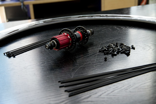
This is how it all begins: a Newsonsportec 40mm Deep V rim, a Novatec F482SBSL rear cassette hub (Shimano, 9-spline Hyperglide), some brass spoke nipples, and a pile of spokes cut to precise lengths according to calculations made with EDD, the online spoke calculator.
(Click to enlarge)
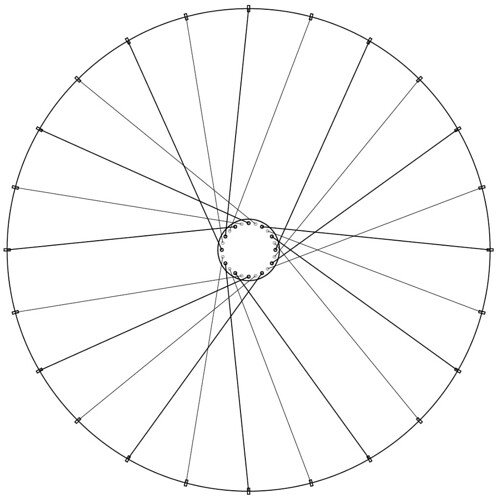
I prepared a scale illustration of the spoke pattern before doing the build. Laying it out this way allowed me to try various combinations of hub diameter, spoke count, and interlacing techniques. It also let me visualize the angles at which the spokes would leave the hub, to ascertain whether a given pattern was buildable or not.
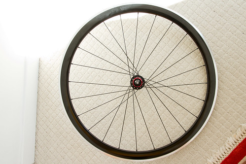
The one that I settled upon was a 24-hole, two-leading two-trailing (2L2T) pattern. On a 24 hole rim (and only on a 24 hole rim) this pattern produces a three-leaved trillium shape. Word to Ontario. The pattern also produces really pronounced parallel lanes between the leaves. I nestled the valve in one of these lanes for easy access when pumping the tires.
(Click to enlarge)
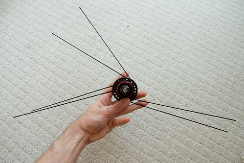
The first step is to thread the drive-side, trailing spokes (the ones that shoot off in the direction opposite from that in which the wheel turns). Here they are, ready to go according to the pattern. There exists some debate about whether the trailing spokes should run along the inside of the hub or the outside of the hub. I ran them on the inside.
(Click to enlarge)
Simply thread the spokes through the correct holes according to the plan, and screw the spoke nipples on enough turns that they won't fall off of their own accord.
Flip the wheel over, and install the trailing spokes of the non-drive side according to the plan. Here are all of the trailing spokes installed, as viewed from the drive-side.
(Click to enlarge)
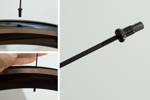
After having installed two sets of trailing spokes, the difficulty level of the wheelbuild increases; you no longer have as much room to move. Because I'm installing spokes on a deep-V rim, this means that I could no longer thread spokes all the way through the rim to the other side, to be able to screw spoke nipples on their ends.
Hence, you need a way to seat the spoke nipples first, then bring the spokes up to them. My technique involved screwing a spoke nipple onto a spare spoke, lightly and backwards, using that spare spoke to drop it into the hole, then unscrewing the spare spoke and lifting it out, leaving the nipple in place.
Whatever you do, you'll likely end up dropping a nipple or two inside the rim, and having to shake it out.
(Click to enlarge)
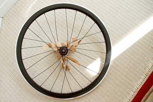
At the point at which you install the leading spokes, you begin to have to cross the spokes in a very calculated way. The established wisdom is that you stay on the outside of the wheel for each of the spokes you cross on the way to the target hole, except for the last crossed spoke, which you cross underneath. I decided to ignore this wisdom and to do something different. If you're really interested, you will have to zoom way in to this photograph to be able to see what's going on.
You have to bend the spokes a tremendous amount to be able to do the interleaving, and things start to get really tight. The pieces of paper are there to prevent the spoke paint from scratching off as spokes begin to rub together. I should have used plastic or foam strips instead, because the spokes tore through the paper pretty easily.
And we're done installing spokes! Time to bring them up to tension.
(Click to enlarge)
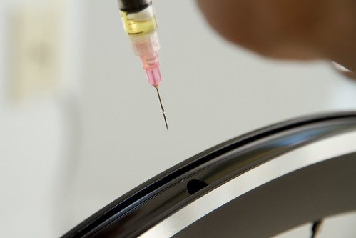
What you want is for a spoke to be very easy to manipulate as you bring it up to tension, then very difficult to adjust when you're finished. For this reason, wheelbuilders use lubricants that dry out over time. I used plain old linseed oil.
I used a syringe to administer the oil. With deep-V rims, this technique is pretty useless; you can't see what's going on in that dark hole, so you can't aim the syringe. For the second wheel, I simply dipped the spoke threads in oil before installing them. It was messier, but it meant the spokes were easier to work with.
(Click to enlarge)
Here's how to proceed.
(Click to enlarge)
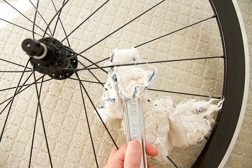
If you've studied materials engineering, you'll be able to cite all kinds of properties of stainless steel, using words like "yield," "cold-formed," "memory," and "plastic deformation," to explain why you need to stress-relieve the spokes in a new wheelbuild. Whether you have or you haven't, grab a cloth and a monkey wrench, and get to work.
Find all of the places where your spokes cross. The idea is to use a wrench as a lever to twist them around each other even more tightly. This may feel wrong. Just do it. The materials engineers say so.
The cloth is just there so you don't scratch the paint off the spokes.
(Click to enlarge)
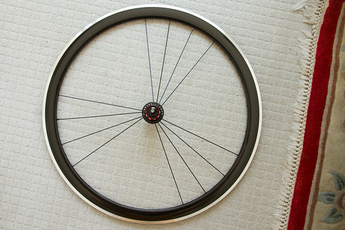
Huzzah! Now that the wheels are done, it's time to tire them up with Presta valve Kenda inner tubes, Vittora Zaffiro Pro tires, and Reynolds rim tape.
Unless your hands are bionic, or you're this guy, you will need a tire iron for the last little bit. Just be aware that your chance of puncturing the inner tube with a tire iron is approximately 100%, unless you keep the inner tube slightly inflated and try your very hardest to avoid pinching it.
Also, pro wheelbuilders pay attention to little details, like making sure that any prominent markings on the tire sit between the same spokes on each wheel. I chose to situate the brand name of the tire directly opposite the valve stem.
Repeat for the front wheel, and that's it!
Next step, truing the wheels – making them spin straight and round.
(Click to enlarge)
(Click to enlarge)
I prepared a scale illustration of the spoke pattern before doing the build. Laying it out this way allowed me to try various combinations of hub diameter, spoke count, and interlacing techniques. It also let me visualize the angles at which the spokes would leave the hub, to ascertain whether a given pattern was buildable or not.
The one that I settled upon was a 24-hole, two-leading two-trailing (2L2T) pattern. On a 24 hole rim (and only on a 24 hole rim) this pattern produces a three-leaved trillium shape. Word to Ontario. The pattern also produces really pronounced parallel lanes between the leaves. I nestled the valve in one of these lanes for easy access when pumping the tires.
(Click to enlarge)
The first step is to thread the drive-side, trailing spokes (the ones that shoot off in the direction opposite from that in which the wheel turns). Here they are, ready to go according to the pattern. There exists some debate about whether the trailing spokes should run along the inside of the hub or the outside of the hub. I ran them on the inside.
(Click to enlarge)
Simply thread the spokes through the correct holes according to the plan, and screw the spoke nipples on enough turns that they won't fall off of their own accord.
Flip the wheel over, and install the trailing spokes of the non-drive side according to the plan. Here are all of the trailing spokes installed, as viewed from the drive-side.
(Click to enlarge)
After having installed two sets of trailing spokes, the difficulty level of the wheelbuild increases; you no longer have as much room to move. Because I'm installing spokes on a deep-V rim, this means that I could no longer thread spokes all the way through the rim to the other side, to be able to screw spoke nipples on their ends.
Hence, you need a way to seat the spoke nipples first, then bring the spokes up to them. My technique involved screwing a spoke nipple onto a spare spoke, lightly and backwards, using that spare spoke to drop it into the hole, then unscrewing the spare spoke and lifting it out, leaving the nipple in place.
Whatever you do, you'll likely end up dropping a nipple or two inside the rim, and having to shake it out.
(Click to enlarge)
At the point at which you install the leading spokes, you begin to have to cross the spokes in a very calculated way. The established wisdom is that you stay on the outside of the wheel for each of the spokes you cross on the way to the target hole, except for the last crossed spoke, which you cross underneath. I decided to ignore this wisdom and to do something different. If you're really interested, you will have to zoom way in to this photograph to be able to see what's going on.
You have to bend the spokes a tremendous amount to be able to do the interleaving, and things start to get really tight. The pieces of paper are there to prevent the spoke paint from scratching off as spokes begin to rub together. I should have used plastic or foam strips instead, because the spokes tore through the paper pretty easily.
And we're done installing spokes! Time to bring them up to tension.
(Click to enlarge)
What you want is for a spoke to be very easy to manipulate as you bring it up to tension, then very difficult to adjust when you're finished. For this reason, wheelbuilders use lubricants that dry out over time. I used plain old linseed oil.
I used a syringe to administer the oil. With deep-V rims, this technique is pretty useless; you can't see what's going on in that dark hole, so you can't aim the syringe. For the second wheel, I simply dipped the spoke threads in oil before installing them. It was messier, but it meant the spokes were easier to work with.
(Click to enlarge)
Here's how to proceed.
- Tighten each spoke nipple with ascrewdriver (slotted through the hole on the outside of the rim) until there are only a few threads showing. I tightened them until there were two threads showing, which ended up being too few; the wheel started to get tight prematurely. Go with three or four.
- Go around the wheel again, this time tightening the spokes with a spoke wrench. Use one full turn on each to start, then fewer turns on each subsequent pass.
- Repeat #2 until the spokes sing a prescribed note when you pluck them. Look up the note for your particular spoke length on this table. My spokes needed to ring between A440 and G#. If you're amusical, then perhaps you should consider cultivating some musical skill; it leads to a richer life, and properly tensioned wheels.
- Detension the spokes, and repeat from #2 as many times as you like.
(Click to enlarge)
If you've studied materials engineering, you'll be able to cite all kinds of properties of stainless steel, using words like "yield," "cold-formed," "memory," and "plastic deformation," to explain why you need to stress-relieve the spokes in a new wheelbuild. Whether you have or you haven't, grab a cloth and a monkey wrench, and get to work.
Find all of the places where your spokes cross. The idea is to use a wrench as a lever to twist them around each other even more tightly. This may feel wrong. Just do it. The materials engineers say so.
The cloth is just there so you don't scratch the paint off the spokes.
(Click to enlarge)
Huzzah! Now that the wheels are done, it's time to tire them up with Presta valve Kenda inner tubes, Vittora Zaffiro Pro tires, and Reynolds rim tape.
Unless your hands are bionic, or you're this guy, you will need a tire iron for the last little bit. Just be aware that your chance of puncturing the inner tube with a tire iron is approximately 100%, unless you keep the inner tube slightly inflated and try your very hardest to avoid pinching it.
Also, pro wheelbuilders pay attention to little details, like making sure that any prominent markings on the tire sit between the same spokes on each wheel. I chose to situate the brand name of the tire directly opposite the valve stem.
Repeat for the front wheel, and that's it!
Next step, truing the wheels – making them spin straight and round.
(Click to enlarge)

 07-16-12, 11:58 AM
#31
Senior Member
Join Date: Apr 2012
Location: Davis, CA
Posts: 88
Bikes: Leader 722ts
Mentioned: 0 Post(s)
Tagged: 0 Thread(s)
Quoted: 1 Post(s)
Likes: 0
Liked 0 Times
in
0 Posts
Can you see your hub label through your valve hole though because that's the most important thing about building a wheel. Naaaaaaaaa just kidding, nice wheels. That 24 hole lacing is interesting did you have to tension the spokes more than a traditional wheel lacing. I assume you wouldn't due to the spoke length but I don't know about the cross. Anyway nice job on the bike keep up the good work.
07-16-12, 12:52 PM
#32
Junior Member
Thread Starter
Conventional wisdom says to lay new spokes over all spokes that you cross on the way to the rim, except for the last one which you duck under. On a 3 cross, this means going over-over-under. On a 2 cross, over-under. Thing is, when you're doing 2-leading 2-trailing wheel, that rule doesn't apply for half of the spokes. Half of the spokes go over-under like you would expect, and half of them go over-NOTHING. Not being confident with having half the spokes interleaved, and half non-interleaved, I simply interleaved them all.
I'll leave the study of this photograph as an exercise for the reader.
01-02-13, 11:50 AM
#33
Junior Member
Thread Starter
Step six: Truing the wheels
Even if you don't own a truing stand or a dishing tool you can still take a good first crack at truing a wheel so that the rims run straight.
I flipped the frame of my bike upside down, installed the wheel in the front fork, and then attached a ruler (metric, natch) to the fork with elastic bands.

(Click to enlarge)
Get the ruler as close to the rim as you can without touching it, then give the wheel a spin. The ruler acts as a fixed reference point against which you can evaluate warps in the rim.
Watch a video of the DIY truing stand in action:
https://www.flickr.com/photos/steveluscher/8338976590/ Using the markings on the ruler and the width of the rim, I was able to roughly calculate where the rim should sit. Wherever the spinning rim would "cross the line" I would tighten the group of spokes opposite that point. Sometimes, instead, I would loosen the group of spokes on the same side as that point, in an effort to maintain the overall A440 tuning of the spokes.
After the rough home-true, I went down to Our Community Bikes to finish the job on their more precise truing stands and dishing tools.
I flipped the frame of my bike upside down, installed the wheel in the front fork, and then attached a ruler (metric, natch) to the fork with elastic bands.
(Click to enlarge)
Get the ruler as close to the rim as you can without touching it, then give the wheel a spin. The ruler acts as a fixed reference point against which you can evaluate warps in the rim.
Watch a video of the DIY truing stand in action:
https://www.flickr.com/photos/steveluscher/8338976590/ Using the markings on the ruler and the width of the rim, I was able to roughly calculate where the rim should sit. Wherever the spinning rim would "cross the line" I would tighten the group of spokes opposite that point. Sometimes, instead, I would loosen the group of spokes on the same side as that point, in an effort to maintain the overall A440 tuning of the spokes.
After the rough home-true, I went down to Our Community Bikes to finish the job on their more precise truing stands and dishing tools.
Last edited by steveluscher; 01-02-13 at 11:59 AM.
01-02-13, 12:31 PM
#34
Junior Member
Thread Starter
Fin
The final step, was to componentize the bike, ride it to vet the build, then to strip the frame down completely for painting.
I sent the frame to the venerable Toxik Harald in Richmond, BC. Harald was Brodie's in-house paint guru in the 90s, and now runs his own shop where he does custom paint jobs. He uses single-stage aircraft paints (color and finish in one), and a custom low-pressure, high-volume gun.
Harald's standard service includes frame stripping, rust removal, and minor frame filling. I asked him to shoot my frame in gloss black. The joint where the frame coupler meets the frame completely disappeared.
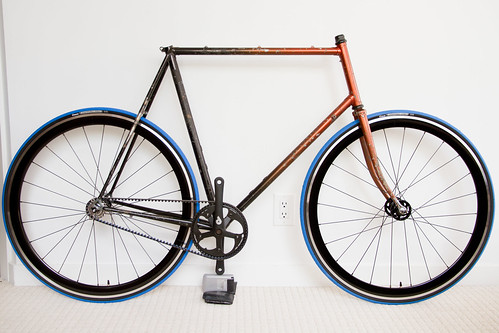
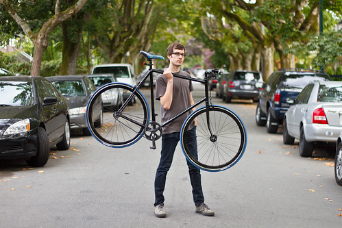
And that's the end of the project! I've been riding this bike for a few months now. It's light, it's smooth, it's clean, and it's quiet.
(Click to enlarge)
I sent the frame to the venerable Toxik Harald in Richmond, BC. Harald was Brodie's in-house paint guru in the 90s, and now runs his own shop where he does custom paint jobs. He uses single-stage aircraft paints (color and finish in one), and a custom low-pressure, high-volume gun.
Harald's standard service includes frame stripping, rust removal, and minor frame filling. I asked him to shoot my frame in gloss black. The joint where the frame coupler meets the frame completely disappeared.
And that's the end of the project! I've been riding this bike for a few months now. It's light, it's smooth, it's clean, and it's quiet.
(Click to enlarge)
01-02-13, 02:05 PM
#36
Crawler

If you are lazy.
https://www.mec.ca/AST/ShopMEC/Cyclin...cle-unisex.jsp
EDIT: FYI, you really need to know what ratio cogs you want to use. Changing them will cost you a lot of $$$.
https://www.mec.ca/AST/ShopMEC/Cyclin...cle-unisex.jsp
EDIT: FYI, you really need to know what ratio cogs you want to use. Changing them will cost you a lot of $$$.
Last edited by linus; 01-02-13 at 02:17 PM.
01-02-13, 09:20 PM
#37
Brown Bear, Sqrl Hunter

This is pretty damn awesome. I skimmed the thread, but what did the total cost come out to?


 01-15-13, 09:54 PM
#40
Senior Member

Join Date: Jan 2012
Location: Ithaca, NY
Posts: 4,852
Bikes: Click on the #YOLO
Mentioned: 1 Post(s)
Tagged: 0 Thread(s)
Quoted: 26 Post(s)
Likes: 0
Liked 12 Times
in
12 Posts
I didn't realize this thread had been updated and concluded. Awesome effort and amazing result.
__________________

Shimano : Click :: Campy : Snap :: SRAM : Bang
Shimano : Click :: Campy : Snap :: SRAM : Bang
01-15-13, 11:00 PM
#41
Junior Member
Thread Starter
It's a delightful mix of junk bin components and splurges. I certainly did it for the experience, and not to save money. 
Thanks Leukybear!
Yeah… I don't get the sense that you could turn a good profit. My bike, for example, had a tapered seatstay, so it's unlikely that an off-the-shelf splitter would have fit.
Thanks Dan!
Thanks Leukybear!
Yeah… I don't get the sense that you could turn a good profit. My bike, for example, had a tapered seatstay, so it's unlikely that an off-the-shelf splitter would have fit.
Thanks Dan!
Last edited by steveluscher; 01-16-13 at 12:42 PM.
01-16-13, 08:24 AM
#42
Member
Join Date: Nov 2012
Posts: 37
Mentioned: 0 Post(s)
Tagged: 0 Thread(s)
Quoted: 0 Post(s)
Likes: 0
Liked 0 Times
in
0 Posts
Nice project and write up! Good job researching the breakaway design - it looks smooth and stiff.
Hipster question - how well does it skid? I'm curious about the belt's response to high shock loads.
Hipster question - how well does it skid? I'm curious about the belt's response to high shock loads.

 01-16-13, 12:41 PM
#46
Junior Member
Thread Starter
Secondly, with respect to whether the belt system could handle it: hell yes. As Dan noted, they use belts to drive these things. Carbon fibre doesn't like to stretch.
01-16-13, 05:26 PM
#47
Member
Join Date: Nov 2012
Posts: 37
Mentioned: 0 Post(s)
Tagged: 0 Thread(s)
Quoted: 0 Post(s)
Likes: 0
Liked 0 Times
in
0 Posts
Hmm... I obviously not did not pay enough attention to the hub used. 
The belt drive concept is really cool, it just doesn't seem "intuitive" for it to behave more like a chain than a rubber band (even knowing quite well how belts behave in other applications). I'd like to ride one. Fixed would be very nice...
The belt drive concept is really cool, it just doesn't seem "intuitive" for it to behave more like a chain than a rubber band (even knowing quite well how belts behave in other applications). I'd like to ride one. Fixed would be very nice...
01-22-13, 11:58 AM
#48
Senior Member
Join Date: Apr 2012
Location: Davis, CA
Posts: 88
Bikes: Leader 722ts
Mentioned: 0 Post(s)
Tagged: 0 Thread(s)
Quoted: 1 Post(s)
Likes: 0
Liked 0 Times
in
0 Posts
wow that build really came out nicely congrats!
the black and blue is a nice touch with the belt drive to.
the black and blue is a nice touch with the belt drive to.
01-22-13, 12:05 PM
#49
Junior Member
Thread Starter