


Internal wiring for dynamo lights: the heads tube connection
 10-28-18, 10:00 AM
#26
Banned
Combining a Schmidt SL dynamo hub with its dropout face contacts,
& inside the fork wiring, fed thru the hollow fork crown?
& inside the fork wiring, fed thru the hollow fork crown?
 10-28-18, 11:25 AM
#27
Senior Member

Join Date: Feb 2008
Location: Peoria, IL
Posts: 4,475
Mentioned: 86 Post(s)
Tagged: 0 Thread(s)
Quoted: 1829 Post(s)
Liked 3,373 Times
in
1,579 Posts
It's concern about breaking carbon brushes while inserting and removing the fork. Electrically there is no doubt they'd be superior.
The commercial carbon brush unit that I modified for prototyping was so overhung that it would have been easy to break; or difficult not to! I considered drilling the center of the brass brush and soldering a round carbon brush in the cavity. Haven't done that but might give it a try on a test piece sometime.
The commercial carbon brush unit that I modified for prototyping was so overhung that it would have been easy to break; or difficult not to! I considered drilling the center of the brass brush and soldering a round carbon brush in the cavity. Haven't done that but might give it a try on a test piece sometime.

Could it be addressed with additional parts that would provide ramped or gradual transitions where the tube/assembly radius changed? Might have to tape over the threads for the headset locknut too.
Alternately, it could use some sort of mechanism to retract the brush when the fork is installed or removed. The Herse had something like this, didn't it? With a down tube mounted brush, this would get tricky! Maybe have to tie a string to the brush and let it dangle out the vent hole in the BB shell, allowing you to pull on the string to retract the brush?? This idea might need a bit of refining, of course.

Steve in Peoria
10-28-18, 11:34 AM
#28
Senior Member
Join Date: Feb 2008
Location: Peoria, IL
Posts: 4,475
Mentioned: 86 Post(s)
Tagged: 0 Thread(s)
Quoted: 1829 Post(s)
Liked 3,373 Times
in
1,579 Posts
Seems like a complicated solution when you could just run a wire from the fork to the back of the bike, though.
Plus, any dynamo is designed to produce more power than a taillight will use, and I'll note that the Velogical is not designed to self-limit to 0.5A even. I entertain myself by coming up with voltage and current regulator designs, but it's probably just one more headache for a normal person.
Steve in Peoria
10-28-18, 11:45 AM
#29


Randomhead
Join Date: Aug 2008
Location: Happy Valley, Pennsylvania
Posts: 24,394
Mentioned: 0 Post(s)
Tagged: 0 Thread(s)
Quoted: 4 Post(s)
Liked 3,694 Times
in
2,516 Posts
I'm a little disappointed that rhm didn't post pics. I guess that means I'm on the hook to post pics if I do this.
I don't understand how the Herse design helps on fork removal, but matters most when you put the fork in the first time.
I just added some HDPE rods to my cart at McMaster to use as an insulator. I think I'm going to try the scheme where the wire is attached to the spring, and physical contact with the brush makes the electrical connection. I am also ordering some graphite filled brass and some phosphor bronze to try as contacts.
Last edited by unterhausen; 10-28-18 at 11:58 AM.
10-28-18, 12:17 PM
#30
Randomhead
Join Date: Aug 2008
Location: Happy Valley, Pennsylvania
Posts: 24,394
Mentioned: 0 Post(s)
Tagged: 0 Thread(s)
Quoted: 4 Post(s)
Liked 3,694 Times
in
2,516 Posts
I had a similar thought... but I was leaning towards the Velogical "bottle" dynamo.
Seems like a complicated solution when you could just run a wire from the fork to the back of the bike, though.
Plus, any dynamo is designed to produce more power than a taillight will use, and I'll note that the Velogical is not designed to self-limit to 0.5A even. I entertain myself by coming up with voltage and current regulator designs, but it's probably just one more headache for a normal person.
If you ever look at the circuits inside dyno lights, most of the good ones are ridiculously complicated. Input protection is key. I had a supernova that disassembled itself, so I looked at the circuitry. It scared me so much I just put it back together and shipped it off to Peter White. Crummy light anyway. I took apart a BuM taillight to remove the fixed ground connection, and it was more complicated than I thought it should be. And that taillight isn't rated to be used by itself without a headlight. I'm still interested in taillight design, but I gave up on headlight design once I became a convert to the joys of shaped beams.
10-28-18, 12:34 PM
#31
Senior Member
The slip ring idea is mostly about cleaning up the bike and an homage to the past, at least for me. For reliability, running a wire externally is the most repairable, but there is some potential for snags. I have never had that kind of problem though, and I run dynos on all my off-road and all-road bikes. I have thought about adding mounting loops for the wire, but never done it. A slip ring is just unfamiliar. I take it that there are examples that have been in service for many decades without issue, so that gives me some confidence. There is a lot to be said for wires completely concealed inside a frame. rhm and I and 50 of our closest friends did a ride at the end of summer where our bikes were transported and moved around by other people. Nothing happened to my bike, but it wasn't without stress.
If you ever look at the circuits inside dyno lights, most of the good ones are ridiculously complicated. Input protection is key. I had a supernova that disassembled itself, so I looked at the circuitry. It scared me so much I just put it back together and shipped it off to Peter White. Crummy light anyway. I took apart a BuM taillight to remove the fixed ground connection, and it was more complicated than I thought it should be. And that taillight isn't rated to be used by itself without a headlight. I'm still interested in taillight design, but I gave up on headlight design once I became a convert to the joys of shaped beams.
If you ever look at the circuits inside dyno lights, most of the good ones are ridiculously complicated. Input protection is key. I had a supernova that disassembled itself, so I looked at the circuitry. It scared me so much I just put it back together and shipped it off to Peter White. Crummy light anyway. I took apart a BuM taillight to remove the fixed ground connection, and it was more complicated than I thought it should be. And that taillight isn't rated to be used by itself without a headlight. I'm still interested in taillight design, but I gave up on headlight design once I became a convert to the joys of shaped beams.
10-28-18, 04:41 PM
#32
Senior Member
Join Date: Feb 2008
Location: Peoria, IL
Posts: 4,475
Mentioned: 86 Post(s)
Tagged: 0 Thread(s)
Quoted: 1829 Post(s)
Liked 3,373 Times
in
1,579 Posts
The slip ring idea is mostly about cleaning up the bike and an homage to the past, at least for me. For reliability, running a wire externally is the most repairable, but there is some potential for snags. I have never had that kind of problem though, and I run dynos on all my off-road and all-road bikes. I have thought about adding mounting loops for the wire, but never done it. A slip ring is just unfamiliar. I take it that there are examples that have been in service for many decades without issue, so that gives me some confidence. There is a lot to be said for wires completely concealed inside a frame. rhm and I and 50 of our closest friends did a ride at the end of summer where our bikes were transported and moved around by other people. Nothing happened to my bike, but it wasn't without stress.
If you ever look at the circuits inside dyno lights, most of the good ones are ridiculously complicated. Input protection is key. I had a supernova that disassembled itself, so I looked at the circuitry. It scared me so much I just put it back together and shipped it off to Peter White. Crummy light anyway. I took apart a BuM taillight to remove the fixed ground connection, and it was more complicated than I thought it should be. And that taillight isn't rated to be used by itself without a headlight. I'm still interested in taillight design, but I gave up on headlight design once I became a convert to the joys of shaped beams.
If you ever look at the circuits inside dyno lights, most of the good ones are ridiculously complicated. Input protection is key. I had a supernova that disassembled itself, so I looked at the circuitry. It scared me so much I just put it back together and shipped it off to Peter White. Crummy light anyway. I took apart a BuM taillight to remove the fixed ground connection, and it was more complicated than I thought it should be. And that taillight isn't rated to be used by itself without a headlight. I'm still interested in taillight design, but I gave up on headlight design once I became a convert to the joys of shaped beams.
I had a touring/commuting/travel frame built by a local-ish fellow back in the year 2000. I knew that I would use a dynamo and needed a better way to route the tail light wires than what I'd been using (velco??). I was leaning towards brazing some M3 nuts onto the top tube, similar to bottle braze-ons, but the builder thought loops were a lot more practical to build. It turned out fine. In retrospect, I should have had some loops on the fork blade too.
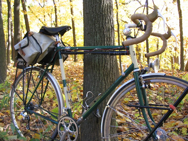
Functionally, it's been fine.
Aesthetically... I really should switch over to using black wires, just to not be so annoying.
Of course, in this photo, the headlight is so ugly that no one would notice the wires. I've gone to a less awful looking headlight housing since.
I could take a better shot of the loops themselves if there is interest.
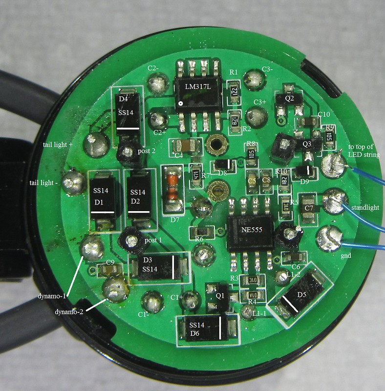
Regarding modern dynamo light complexity and design, I fixed a Supernova Triple headlight for a fellow about a year ago. There was a lot of damage (the lesson is to not hook it up to an E-bike battery), so I had to reverse engineer the whole thing, as well as replace most of the semiconductors.
Overall, I was impressed with the quality of the design and materials. Very nice! It resembled industrial electronics instead of the commercial type of construction of B&M lights.
The circuit design used parts that were very standard and common. That made repair practical. No microcontroller, which meant that there were no fancy or confusing modes of operation.
Here's a shot of the circuit board. If anyone needs/wants to see the schematic, please PM me.
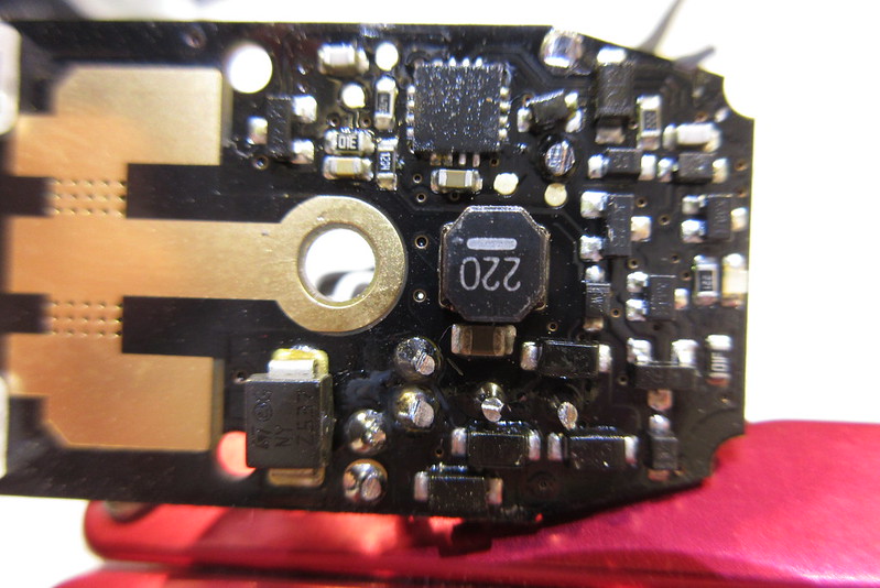
On the cheaper, more commercial end of the spectrum, I've got a dead B&M Eyc that I hope to use for experiments (hopefully the experiments won't be too gruesome.
)It's a tiny light, but the circuit board still uses a microcontroller, a light sensor (IIRC), and a lighted switch. The parts are all quite modern and small; i.e. not practical to repair.
Too bad that they don't use some conformal coating to keep moisture off of the board, or use a water-tight housing.
here's a poor photo of the circuit board:
I haven't touched this since the weather became suitable for riding lots of miles. My hope is to get back to it soon.
Steve in Peoria
10-28-18, 04:49 PM
#33
Randomhead
Join Date: Aug 2008
Location: Happy Valley, Pennsylvania
Posts: 24,394
Mentioned: 0 Post(s)
Tagged: 0 Thread(s)
Quoted: 4 Post(s)
Liked 3,694 Times
in
2,516 Posts
Since it was being warrantied, I didn't want to mess with the Supernova too much, but it was much more complex than the board you show. They used smaller series of surface mount than that too. It was a single led light. They do have a nice voltage doubler, about the only part I like about them. Not sure why the case is so big, I got the "Pure" model without the switch and hopefully some of the baggage is gone. It's still not a very good light in comparison to the BuM lights. But I know what you are talking about, BuM electronics look cheap and the mechanical design is poor.
10-29-18, 08:45 AM
#34

multimodal commuter
Thread Starter

Join Date: Nov 2006
Location: NJ, NYC, LI
Posts: 19,808
Bikes: 1940s Fothergill, 1959 Allegro Special, 1963? Claud Butler Olympic Sprint, Lambert 'Clubman', 1974 Fuji "the Ace", 1976 Holdsworth 650b conversion rando bike, 1983 Trek 720 tourer, 1984 Counterpoint Opus II, 1993 Basso Gap, 2010 Downtube 8h, and...
Mentioned: 584 Post(s)
Tagged: 0 Thread(s)
Quoted: 1908 Post(s)
Liked 574 Times
in
339 Posts
My apologies for not taking photos. I meant to -- but then suddenly the thing was together and I was sick of the project and I hadn't taken any photos yet. Doh!
I will be coming back to this when I have a little more time and patience, and will take photos then.
Thanks for all the replies, some very interesting ideas there.
I've been googling and searching for any sign of the Shimano rear wheel dynamo hubs that used to be available, and (just as I thought perhaps I had been hallucinating) I found this:
https://www.amazon.co.uk/SHIMANO-NEX.../dp/B01N554ODJ
__________________
www.rhmsaddles.com.
www.rhmsaddles.com.
10-29-18, 09:13 AM
#35
Randomhead
Join Date: Aug 2008
Location: Happy Valley, Pennsylvania
Posts: 24,394
Mentioned: 0 Post(s)
Tagged: 0 Thread(s)
Quoted: 4 Post(s)
Liked 3,694 Times
in
2,516 Posts
Yes, you see those on ebay occasionally. It's for a comfort bike that shifts itself. They didn't want people to have to worry about batteries. Not sure how much power it puts out though. AFAIK, it was never sold in North America.
10-29-18, 09:41 AM
#36
multimodal commuter
Thread Starter
Join Date: Nov 2006
Location: NJ, NYC, LI
Posts: 19,808
Bikes: 1940s Fothergill, 1959 Allegro Special, 1963? Claud Butler Olympic Sprint, Lambert 'Clubman', 1974 Fuji "the Ace", 1976 Holdsworth 650b conversion rando bike, 1983 Trek 720 tourer, 1984 Counterpoint Opus II, 1993 Basso Gap, 2010 Downtube 8h, and...
Mentioned: 584 Post(s)
Tagged: 0 Thread(s)
Quoted: 1908 Post(s)
Liked 574 Times
in
339 Posts
Right, I remembered looking at the specifications and thinking it was much too low for my purposes. But at the time I was thinking of powering head and tail light. But if it's enough to power a tail light, it solves some troublesome wiring problems and leaves more power for the headlight and charging GPS, phone, etc.
10-29-18, 11:24 AM
#37
Randomhead
Join Date: Aug 2008
Location: Happy Valley, Pennsylvania
Posts: 24,394
Mentioned: 0 Post(s)
Tagged: 0 Thread(s)
Quoted: 4 Post(s)
Liked 3,694 Times
in
2,516 Posts
If all I wanted was a reliable way to get power to the back, I would stick with my current setup of BuM two conductor wire and clear Gorilla repair tape. The tape does get ugly after a while, even when I use latex gloves to put it on. I have also used the coax Supernova wire, it's a bit nicer. I bought some of the frame plugs for Di2 wires, so internal routing with a loop of wire at the headset is also something I have considered. I would like to have a loop for attaching the wire inside the bb shell.
10-29-18, 08:35 PM
#38
Senior Member
If it's like the later ones that shifted a 3 speed nexus, it's 3v1.5w.
10-30-18, 01:20 PM
#39
Randomhead
Join Date: Aug 2008
Location: Happy Valley, Pennsylvania
Posts: 24,394
Mentioned: 0 Post(s)
Tagged: 0 Thread(s)
Quoted: 4 Post(s)
Liked 3,694 Times
in
2,516 Posts
here is a Hirose video where he wires up a bike for head tube connections.
mostly a collection of stills. Starts at about 3 minutes in
11-07-18, 08:13 PM
#40
Randomhead
Join Date: Aug 2008
Location: Happy Valley, Pennsylvania
Posts: 24,394
Mentioned: 0 Post(s)
Tagged: 0 Thread(s)
Quoted: 4 Post(s)
Liked 3,694 Times
in
2,516 Posts
I just got my plastic in today. Bought it from McMaster, and they only have 8 foot lengths, which ran the shipping cost up quite a bit. Now I have a lifetime supply.
11-08-18, 02:17 PM
#41
Randomhead
Join Date: Aug 2008
Location: Happy Valley, Pennsylvania
Posts: 24,394
Mentioned: 0 Post(s)
Tagged: 0 Thread(s)
Quoted: 4 Post(s)
Liked 3,694 Times
in
2,516 Posts
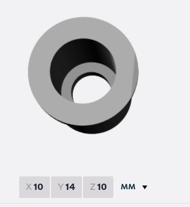
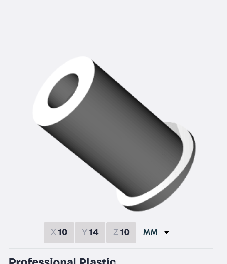
rhm pointed out that a holder for the plunger to go in the head tube could be 3d printed. So I made a solid model. It's made to conform to the ID of a 1 1/4" head tube. Maybe if you have a bike boom raleigh it will have to be shaped a little to conform to the head tube material that they found at the scrap yard. 8mm outer diameter, 6mm inner diameter. About $7.50 on shapeways. Didn't figure out how to make it publicly available. Length/diameter changes are trivial. The idea is to press or glue this into the head tube. The inner face would have to be cleaned up. I was thinking a sanding drum on a dremel.
11-09-18, 11:55 AM
#42
Banned
Generally the red LED, dont draw that much power , so a freestanding battery tail light should be fine
at night, for weeks.
even bulb tail lights in generator sets , got just 0.6w of the 3w output.
...
at night, for weeks.
even bulb tail lights in generator sets , got just 0.6w of the 3w output.
...
11-11-18, 11:21 AM
#43

Bike Butcher of Portland

Join Date: Jul 2014
Location: Portland, OR
Posts: 11,634
Bikes: It's complicated.
Mentioned: 1299 Post(s)
Tagged: 0 Thread(s)
Quoted: 4678 Post(s)
Liked 5,795 Times
in
2,281 Posts
Rudi asked me to measure the HT vent holes on my collection of Raleigh frames. I�m away for the weekend, I�ll try and measure them when I get back.
Likes For gugie:
11-11-18, 11:47 AM
#44
Randomhead
Join Date: Aug 2008
Location: Happy Valley, Pennsylvania
Posts: 24,394
Mentioned: 0 Post(s)
Tagged: 0 Thread(s)
Quoted: 4 Post(s)
Liked 3,694 Times
in
2,516 Posts
Thanks, I need to take the forks out of some of my bikes to look. I plan on making a variety of designs and glom them together at the base to save on printing cost. The minimum charge seems to be $5 or $7.50 depending on what plastic you choose. I think a lot of vent holes are 1/4"; at least that is what I have always used. So I'm going to make a 6mm version as well as the 8mm version. Rudi came up with the idea of making it square so it can be trimmed more easily. 4mm square and 3mm brushes are readily available, so I am working with those sizes right now. I suspect 4mm square brass rod is available too, and that might work better for rinko. 4mm is pretty close to 5/32"
Okay, a quick google search didn't show up any sources of 4mm brass bar stock, so that might be a problem. But I didn't look that hard.
Okay, a quick google search didn't show up any sources of 4mm brass bar stock, so that might be a problem. But I didn't look that hard.
Last edited by unterhausen; 11-11-18 at 11:52 AM.
11-11-18, 02:22 PM
#45
Senior Member
@unterhausen was there a reason you weren't looking for 5/32 stock? Seems they sell it here.
11-11-18, 05:11 PM
#46
Randomhead
Join Date: Aug 2008
Location: Happy Valley, Pennsylvania
Posts: 24,394
Mentioned: 0 Post(s)
Tagged: 0 Thread(s)
Quoted: 4 Post(s)
Liked 3,694 Times
in
2,516 Posts
thanks for the link, I ran out of energy before I dived into searching on their website. I figured I would find it eventually.
Also, thanks for the light
Also, thanks for the light
11-12-18, 08:29 AM
#47
Randomhead
Join Date: Aug 2008
Location: Happy Valley, Pennsylvania
Posts: 24,394
Mentioned: 0 Post(s)
Tagged: 0 Thread(s)
Quoted: 4 Post(s)
Liked 3,694 Times
in
2,516 Posts
If possible, it would be nice to know the ID of the head tubes. I am not sure if a telescoping hole gauge will fit past a headset when extended.
11-12-18, 10:39 AM
#48
multimodal commuter
Thread Starter
Join Date: Nov 2006
Location: NJ, NYC, LI
Posts: 19,808
Bikes: 1940s Fothergill, 1959 Allegro Special, 1963? Claud Butler Olympic Sprint, Lambert 'Clubman', 1974 Fuji "the Ace", 1976 Holdsworth 650b conversion rando bike, 1983 Trek 720 tourer, 1984 Counterpoint Opus II, 1993 Basso Gap, 2010 Downtube 8h, and...
Mentioned: 584 Post(s)
Tagged: 0 Thread(s)
Quoted: 1908 Post(s)
Liked 574 Times
in
339 Posts
I measured a hand made US frame from about 2000 -- a cyclocross frame by Scott Quiring-- and the vent hole in that is 10 mm.
Don't head tube ID's have to be standard, so that headset cups fit them?
https://www.sheldonbrown.com/cribsheet-headsets.html
Don't head tube ID's have to be standard, so that headset cups fit them?
https://www.sheldonbrown.com/cribsheet-headsets.html
__________________
www.rhmsaddles.com.
www.rhmsaddles.com.
Last edited by rhm; 11-12-18 at 10:42 AM.
11-12-18, 11:04 AM
#49
Randomhead
Join Date: Aug 2008
Location: Happy Valley, Pennsylvania
Posts: 24,394
Mentioned: 0 Post(s)
Tagged: 0 Thread(s)
Quoted: 4 Post(s)
Liked 3,694 Times
in
2,516 Posts
no, they aren't standard. Cheap bikes will have thicker head tubes. The top and bottom of the head tube are bored out with a facing tool. Not sure what the max variation is. I was being silly about Raleigh, but lore has it that most large manufacturers would slip in a crummy tube now and again if it was expedient. It would be funny in the case of Raleigh, since at one time they were part of the same conglomerate as Reynolds.
I think the square design will handle a 10mm hole. but I think I need to add triangles on the side if I can't convince people to glue them in.
I just ordered some 4mm square carbon brushes from Amazon.
I think the square design will handle a 10mm hole. but I think I need to add triangles on the side if I can't convince people to glue them in.
I just ordered some 4mm square carbon brushes from Amazon.
11-13-18, 10:36 AM
#50
Randomhead
Join Date: Aug 2008
Location: Happy Valley, Pennsylvania
Posts: 24,394
Mentioned: 0 Post(s)
Tagged: 0 Thread(s)
Quoted: 4 Post(s)
Liked 3,694 Times
in
2,516 Posts
I got the brushes. Most common dimension is 3.93mm. Two of them were 4mm in one dimension, 3.9-ish in the other dimension. I feel like 4mm might be the best choice of hole size.