


Paul B aligning vid
 02-20-21, 11:49 PM
#1

Senior Member
Thread Starter
Join Date: Feb 2012
Location: Rochester, NY
Posts: 18,056
Bikes: Stewart S&S coupled sport tourer, Stewart Sunday light, Stewart Commuting, Stewart Touring, Co Motion Tandem, Stewart 3-Spd, Stewart Track, Fuji Finest, Mongoose Tomac ATB, GT Bravado ATB, JCP Folder, Stewart 650B ATB
Mentioned: 0 Post(s)
Tagged: 0 Thread(s)
Quoted: 4195 Post(s)
Liked 3,837 Times
in
2,295 Posts
Paul B aligning vid
Some of this I do. Some is not my view. But all is interesting to watch. Both budding and brother builders will smile, check it out. Andy
__________________
AndrewRStewart
AndrewRStewart

Likes For Andrew R Stewart:
02-21-21, 08:56 AM
#2


Randomhead
Join Date: Aug 2008
Location: Happy Valley, Pennsylvania
Posts: 24,386
Mentioned: 0 Post(s)
Tagged: 0 Thread(s)
Quoted: 4 Post(s)
Liked 3,687 Times
in
2,510 Posts
I'll watch it sometime. I have intended to go to a head tube based alignment check because the bb shell is somewhat inadequate as a reference. And I have a bench center collecting dust. But then you have to check the bb shell alignment separately
02-21-21, 10:38 AM
#3
Team Beer
Join Date: Apr 2004
Location: Sacramento CA
Posts: 6,339
Bikes: Too Many
Mentioned: 3 Post(s)
Tagged: 0 Thread(s)
Quoted: 114 Post(s)
Liked 159 Times
in
104 Posts
It was intriguing to watch. I've only used lugged BB shells so far so the table method and flipping hasn't been an issue for me. I do use his method for the rear triangle. Anyone know what BB cups he uses to protect the shell in the vice? I'm assuming they are old BB cups with the threads ground down.
__________________
I'm not one for fawning over bicycles, but I do believe that our bikes communicate with us, and what this bike is saying is, "You're an idiot." BikeSnobNYC
I'm not one for fawning over bicycles, but I do believe that our bikes communicate with us, and what this bike is saying is, "You're an idiot." BikeSnobNYC
02-21-21, 10:57 AM
#4
Senior Member
Join Date: Dec 2019
Posts: 954
Mentioned: 3 Post(s)
Tagged: 0 Thread(s)
Quoted: 321 Post(s)
Liked 263 Times
in
212 Posts
I'm still not convinced of the merit of trying to bend the ST or DT to make them perpendicular to the BB shell on a welded frame because you're just going to end up with (slightly) bent tubes. Doug said in another thread that on a lugged frame the lug might bend and the tube stay straight, which would be a much more desirable outcome.
If you are going to align the ST by bending it you need to put a seatpost or some kind of extension in so that you're measuring its height off the table at the right point. If it's not straight that height is no longer the same all along. If it's the right height just below the top of the ST (where people usually measure it) then by the time you get to the actual seat it will be going too far the other way.
I'd also be tempted to measure everything on the frame, decide what was out and what corrections to attempt before getting the car jack out. My own experience has been that if everything is fixtured correctly the front triangle does not twist or move measurably (by me, with string + eye). But out of only 6 frames perhaps I just got lucky. Rear triangle realignments however are inevitable, easy to do, and it's fine if it's the stays that bending. In fact that's what you expect especially after the bridge tubes have gone in.
02-21-21, 12:26 PM
#5
Randomhead
Join Date: Aug 2008
Location: Happy Valley, Pennsylvania
Posts: 24,386
Mentioned: 0 Post(s)
Tagged: 0 Thread(s)
Quoted: 4 Post(s)
Liked 3,687 Times
in
2,510 Posts
I don't extend the head tube to see if it's twisted. I check both ends and it hasn't been out so much that I can detect it. I did have one frame I built a while back that had the bb shell a little catywumpus to the whole front triangle, so bending that back into shape could be done with a bar down the seat tube. The most recent frame just needed the chain stays moved around a little, I'm working on my fixture to see if I can fix that problem.
I don't thing a lugged front triangle with a twist in the head tube can be fixed too easily. I once saw a video of a Japanese builder doing it by witch wanding, That might be the most successful method.
I don't thing a lugged front triangle with a twist in the head tube can be fixed too easily. I once saw a video of a Japanese builder doing it by witch wanding, That might be the most successful method.
Likes For unterhausen:
02-21-21, 01:13 PM
#6
Senior Member
Join Date: Aug 2007
Location: Evanston, IL
Posts: 5,084
Bikes: many
Mentioned: 63 Post(s)
Tagged: 0 Thread(s)
Quoted: 1441 Post(s)
Liked 1,386 Times
in
758 Posts
Also, if anybody has a reference for the Pop Hodge blog post, I would appreciate a link. The last time I went looking I couldn't find it.
* It still boggles my mind if I think too deeply about the time covered by the overlapping careers of Pop Hodge and Dave Moulton, probably over 85 years.
02-21-21, 02:38 PM
#7
Senior Member
Join Date: Dec 2019
Posts: 954
Mentioned: 3 Post(s)
Tagged: 0 Thread(s)
Quoted: 321 Post(s)
Liked 263 Times
in
212 Posts
As "not a framebuilder," I'm curious about the magnitude these terms represent. I ask because... I recall a Dave Moulton blog post (I think) from several years ago where he described learning framebuilding from Pop Hodge.* As I recall, he described laying out the frame on the shop's brick floor. That would represent the extreme of catywumpus I suspect. (I also suspect Pop Hodge's frames were mostly built for a different clientele than today's modern builders.)
Also, if anybody has a reference for the Pop Hodge blog post, I would appreciate a link. The last time I went looking I couldn't find it.
* It still boggles my mind if I think too deeply about the time covered by the overlapping careers of Pop Hodge and Dave Moulton, probably over 85 years.
Also, if anybody has a reference for the Pop Hodge blog post, I would appreciate a link. The last time I went looking I couldn't find it.
* It still boggles my mind if I think too deeply about the time covered by the overlapping careers of Pop Hodge and Dave Moulton, probably over 85 years.
A Reynolds frame tube has a straightness tolerance of about 1.5mm TIR ("Total Indicator Reading"). I think that means if you lay it down flat one end can be up to 1.5mm higher than the other. That would be about 0.14 degrees. People trying to align frames to super-high tolerances ought to be measuring this stuff or the corrections they're making may not actually be helping.
When they laid things out on the shop floor they may have just realigned the frames afterwards I guess, although this is not ideal.
These tolerances of around a mm or so over half a metre are the best you're going to get with a structure made like a bike frame, and plenty good enough. The tubes themselves are made to that kind of tolerance and you are always going to get some distortion from the heat, although this can be managed. Most of it affects the rear triangle in an obvious way and that can be corrected for. But what you can see with a good eye and measure with string is in this 1mm over 0.5m sort of range.
The lengths of the tubes and the angles are going to be a similar kind of tolerance if the frame is hand-made. I measure where I want to cut with a metre ruler, make a mark with a sharpie, and put my mitre template on. When it comes to the last tube in a loop (the TT and the SS) I start a little bit long and sneak up on the right length to make the angles right as measured with my Chinesium digital angle box. But idk how accurate that really is, and if the reading is off by a tenth of a degree or so I don't fuss about it (the display is probably more precise than the actual tool is accurate).
When you make something you try to make it as perfect as you can but TBH it can probably be off by a good deal before it will really affect the riding. But if it's visibly off like the wheel is closer to one stay than the other etc. that will quite rightly bug the hell out of you.
There are much tighter tolerances for the facing of the HT and the BB shell and the IDs of the HT and the ST-- about 0.2mm or so. That's why you need to machine those.
You could make a much finer toleranced bike if you machined the whole thing from billet aluminium like these guys: https://polebicycles.com/machine/. But unless you're planning on riding it around the inside of a stellerator fusion reactor I don't think it's going to make any difference in the real world (tolerances aren't the reason Pole machine their frames-- it's so they can use 7000 series aluminium which isn't weldable).
02-21-21, 03:59 PM
#8
blahblahblah chrome moly

Join Date: Apr 2009
Location: Seattle
Posts: 1,984
Mentioned: 92 Post(s)
Tagged: 0 Thread(s)
Quoted: 1172 Post(s)
Liked 2,566 Times
in
1,072 Posts
As "not a framebuilder," I'm curious about the magnitude these terms represent. I ask because... I recall a Dave Moulton blog post (I think) from several years ago where he described learning framebuilding from Pop Hodge.* As I recall, he described laying out the frame on the shop's brick floor. That would represent the extreme of catywumpus I suspect. (I also suspect Pop Hodge's frames were mostly built for a different clientele than today's modern builders.)
Also, if anybody has a reference for the Pop Hodge blog post, I would appreciate a link. The last time I went looking I couldn't find it.
* It still boggles my mind if I think too deeply about the time covered by the overlapping careers of Pop Hodge and Dave Moulton, probably over 85 years.
Also, if anybody has a reference for the Pop Hodge blog post, I would appreciate a link. The last time I went looking I couldn't find it.
* It still boggles my mind if I think too deeply about the time covered by the overlapping careers of Pop Hodge and Dave Moulton, probably over 85 years.

(Spotted in the workshop of Martin Molin, of Wintergatan MMX fame (off-topic))
Mark B in Seattle
02-21-21, 05:46 PM
#9
blahblahblah chrome moly
Join Date: Apr 2009
Location: Seattle
Posts: 1,984
Mentioned: 92 Post(s)
Tagged: 0 Thread(s)
Quoted: 1172 Post(s)
Liked 2,566 Times
in
1,072 Posts
It seems to me that the two methods of alignment are equivalent and will give the same results, if the parts (frame and table) are all really "to spec", and stay that way through the alignment process.
For one thing, a BB shell facing tool doesn't really bring the faces to parallel, because all such tools have a little slop and flex in them, which allows the facer to flop over a bit. It will flop away from the side that starts cutting first, so the resulting cut is somewhere between spec and where it was originally. I.e. the facer improves it some but not all the way. The Campy facer is the best I've used (least slop, least flex) and plenty good enough IMHO, but most others I've used had too much slop for the faces to be a good datum for aligning. Even with a Campy you need to remember that your faces are not 100% parallel.
Next is the table flatness and how close the BB holding post is to "normal" (perpendicular in every plane that passes through the BB axis). The table in the Brodie video has a pretty wimpy BB post. The fact that it moved while Brodie aligned a frame is pretty damning. Attaching to the table by only one bolt seems inadequate to me. I know lots of guys have BB posts made this way and get adequate results, but I was spoiled by really mondo posts at the last few places I worked. The table at Ti Cycles is a good example, you can see it on their website. Look at where it bolts to the thick granite table, with four large bolts widely spaced from each other. The central post is joined to the bottom plate (where the bolts are) by a welded pyramid made of four fairly thick plates. The whole thing was faced on its bottom surface in a lathe after welding. (I assume anyway; I wasn't there when it was made. Coulda been done on a milling machine, but a lathe would be logical.) Bottom line is when you align a frame and then flip it, the frame is still aligned!
Another factor that can creep in is the BB faces can squirm a bit on the post, so I tended to loosen and re-tighten the shell on the post after a big heave. I did get different readings before and after retightening, so this is not just theoretical — the shell does squirm where it's clamped. More with Ti frames, but some with steel. Probably the squirm can be minimized with proper post design, but it's something to check for.
I have considered making a BB post that utilizes the Campy threaded inserts that are part of the facing tool. That would give you a good datum for alignment if the post was a precision fit on the ID of the Campy inserts. Downside is needing to fully tap the threads before aligning, which wouldn't work for some workflows, like if you do an alignment check after tacking but before final brazing/welding. Also it'd be very slow, annoying if you're trying to make a living. The opposite of that was the Bike Machinery table at Davidson, that clamped the BB shell faces pneumatically with a foot-pedal, fast and repeatable but $$ and complexity = more things that can go wrong.
Another disadvantage of using the Campy facing inserts for alignment is that the ID is a bit small for my taste as an alignment post. The central "bolt" on the Ti Cycles post is very large diameter, I don't remember the number, but basically as large as it can be and still fit through a BSC threaded shell. I haven't decided yet whether strength is the only thing that matters there, or whether stiffness matters too. Say if you made a small-diameter post out of heat-treated super tool steel that is plenty strong enough, would the springiness of the post adversely affect the alignment? Extra spring in the post would definitely mean you have to move the thing being aligned further to get it to take a set, but that isn't necessarily a deal-breaker, and I'm sure you'd adapt quickly with practice. It could mean you'd need to elevate the frame centerplane higher above the table to avoid bottoming out, especially with Ti. But there's no such thing as too stiff, so the largest possible diameter for the post is probably best.
One reason to use the BB faces as your datum is if you're wholesaling frames to dealers — some of them may have an alignment table, like a New England Cycling Academy (NRCA) or Bringheli. At Davidson we aligned them to the nth degree, not because that's necessary for "riding good", but more as a sales gimmick. If someone checked our frame they'd be impressed, and sell more of them. Of course there's still that whole can o' worms: is their alignment fixture any good? If theirs disagrees with yours, can you convince them that the problem is with their fixture? Very few dealers have such a thing, but we had a few that did, and word gets around.
Again if both methods are highly refined, then there shouldn't be any difference in results regardless of what you choose as your datum.
Mark B in Seattle
Last edited by bulgie; 02-21-21 at 06:33 PM.
02-21-21, 11:18 PM
#10
Senior Member
Thread Starter
Join Date: Feb 2012
Location: Rochester, NY
Posts: 18,056
Bikes: Stewart S&S coupled sport tourer, Stewart Sunday light, Stewart Commuting, Stewart Touring, Co Motion Tandem, Stewart 3-Spd, Stewart Track, Fuji Finest, Mongoose Tomac ATB, GT Bravado ATB, JCP Folder, Stewart 650B ATB
Mentioned: 0 Post(s)
Tagged: 0 Thread(s)
Quoted: 4195 Post(s)
Liked 3,837 Times
in
2,295 Posts
Mark's above comments are much what i thought watching the vid. I say that alignment table at one of the frame builder shows (forget which one) and wondered why they removed so much table material (well I guess it's for weight but I haven't had to pedal my cast steel surface plate up a hill ever )
)
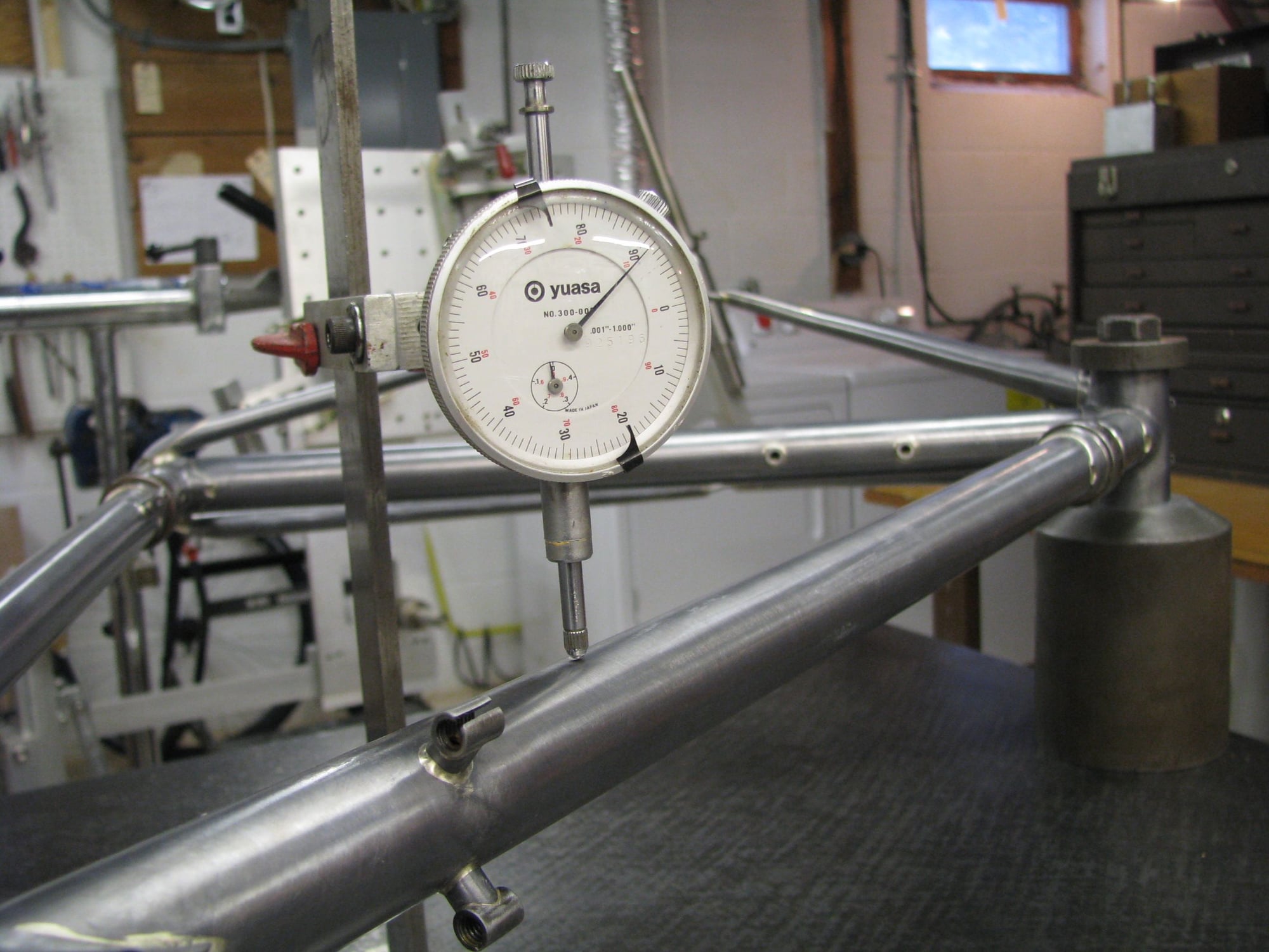
In the vid Paul ponders about the whipping post allowing the shell to float about and seems to suggest this is bad. I wonder about that though. Mark ponders about using an insert in the shell (like the Campy facing guides) but says nothing about the thread clearances having some possible slop. I suppose if you really wanted to use the shell's bore to be your datum some way of really securing the guides in place and also not have the post touch the shell's faces at all, ever. On my own self designed post the top cap has a step to more easily locate the shell somewhat coaxially to the post. In the many frames I've had on the table I don't see any real life issues with the tiny amount of slop that a slip fit cap allows for.
I do agree with Paul on removing a frame and flipping it will bring up different measurements (not that Paul measured anything during his aligning work, he was using gages, not rulers and dial indicators). I also find the same drift of measurements happens when the frame is removed and replaced without flipping it. But a few thousandths of an inch of drift is a pretty much non issue, IMO.
I also agree with Mark on the tubes and shells not being perfect to begin with. I frequently see a tube's straightness change at the butt transitions and even straight gage tubes have some bow in their lengths.
Three quotes come to mind. "Show me a perfect person and I'll build a perfect frame for them" (A Eisentraut at the last VT building class in 1979), "What's a few thousandths between friends" (claimed to be the reply from the guy who did the sample run of a new component which would have changed front shifting as we knew it. The samples were so poor working that no manufacturer paid much attention), and "Just because you can measure a thousandth of an inch doesn't make it important" (me).
I use a pair of 5/16" thick steel plates when doing any heavy work in the vise. It looks to my eye that Paul's things are turned pucks with a step in their OD. The step fits loosely in the shell and makes moving the frame about in the vise jaws far easier then with my flat plates.
Here's a shot of my post. The bolt is a simple V thread 1/2x13tpi . Andy
)In the vid Paul ponders about the whipping post allowing the shell to float about and seems to suggest this is bad. I wonder about that though. Mark ponders about using an insert in the shell (like the Campy facing guides) but says nothing about the thread clearances having some possible slop. I suppose if you really wanted to use the shell's bore to be your datum some way of really securing the guides in place and also not have the post touch the shell's faces at all, ever. On my own self designed post the top cap has a step to more easily locate the shell somewhat coaxially to the post. In the many frames I've had on the table I don't see any real life issues with the tiny amount of slop that a slip fit cap allows for.
I do agree with Paul on removing a frame and flipping it will bring up different measurements (not that Paul measured anything during his aligning work, he was using gages, not rulers and dial indicators). I also find the same drift of measurements happens when the frame is removed and replaced without flipping it. But a few thousandths of an inch of drift is a pretty much non issue, IMO.
I also agree with Mark on the tubes and shells not being perfect to begin with. I frequently see a tube's straightness change at the butt transitions and even straight gage tubes have some bow in their lengths.
Three quotes come to mind. "Show me a perfect person and I'll build a perfect frame for them" (A Eisentraut at the last VT building class in 1979), "What's a few thousandths between friends" (claimed to be the reply from the guy who did the sample run of a new component which would have changed front shifting as we knew it. The samples were so poor working that no manufacturer paid much attention), and "Just because you can measure a thousandth of an inch doesn't make it important" (me).
I use a pair of 5/16" thick steel plates when doing any heavy work in the vise. It looks to my eye that Paul's things are turned pucks with a step in their OD. The step fits loosely in the shell and makes moving the frame about in the vise jaws far easier then with my flat plates.
Here's a shot of my post. The bolt is a simple V thread 1/2x13tpi . Andy
__________________
AndrewRStewart
AndrewRStewart
Likes For Andrew R Stewart:
02-22-21, 02:40 PM
#11
Senior Member
Join Date: Aug 2012
Location: Seattle
Posts: 507
Mentioned: 0 Post(s)
Tagged: 0 Thread(s)
Quoted: 103 Post(s)
Liked 144 Times
in
88 Posts
Agree with him or not, Paul is still more interesting and enjoyable than most stuff on TV !
My post fits very snugly in a BSC BB shell. If there's any flux/tube sticking into the shell, it won't fit. That has worked very well for me. I have considered making a sleeve for T47.
When I bought the post, i ended up getting an older full set of Alex Meade's frame fixture kit. I use the HT stand-offs to measure twist. I lock the HT in the stand-offs with cones and then support the ST with a machinist jack and measure the variation along the seattube. I'd like something more robust like bench centers like Jamie Swan uses but that seems like a project in itself to set up. I can flip the frame on the post and get reasonably close measurements so, this isn't an area I will invest much more energy in in the short term.
One time I loaded the frame onto the post while the shell was still hot and I measured and it was off pretty bad. I wandered around swearing at myself trying to replay the miter and brazing sequence to see where I could have caused the problem. Then went back to look at it again to confirm my thinking only to find that it had cooled into near perfect position. It had moved like 5-6mm at end of the seattube.
__________________
https://www.flickr.com/photos/54319503@N05/
https://www.draper-cycles.com
https://www.flickr.com/photos/54319503@N05/
https://www.draper-cycles.com
Likes For duanedr:
02-22-21, 10:07 PM
#12
Senior Member
Thread Starter
Join Date: Feb 2012
Location: Rochester, NY
Posts: 18,056
Bikes: Stewart S&S coupled sport tourer, Stewart Sunday light, Stewart Commuting, Stewart Touring, Co Motion Tandem, Stewart 3-Spd, Stewart Track, Fuji Finest, Mongoose Tomac ATB, GT Bravado ATB, JCP Folder, Stewart 650B ATB
Mentioned: 0 Post(s)
Tagged: 0 Thread(s)
Quoted: 4195 Post(s)
Liked 3,837 Times
in
2,295 Posts
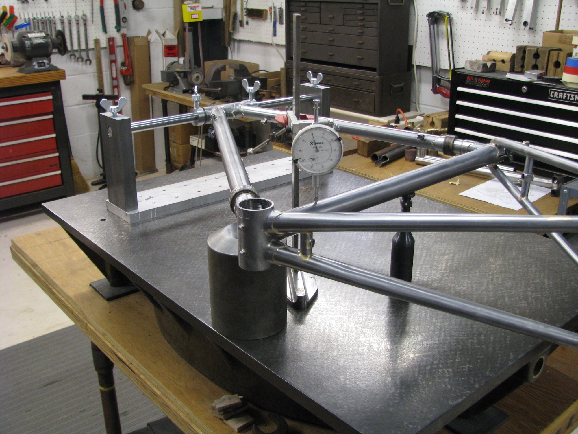
To Tangent- My headtube holding set up for the flat plate was made by Alex Meade. The two towers were about .001" different heights! Close enough for horse shoes, nuclear bombs and bike frames. I placed a .002" shim under the taller side and a .003" one under the shorter's base. Here's a shot with it, note the whipping post is just looking on. It's thinking to it's self "who does that pretty thing think it is? All shinny and useless to do any real work?" Andy
__________________
AndrewRStewart
AndrewRStewart
Likes For Andrew R Stewart:
02-22-21, 11:57 PM
#13
Team Beer
Join Date: Apr 2004
Location: Sacramento CA
Posts: 6,339
Bikes: Too Many
Mentioned: 3 Post(s)
Tagged: 0 Thread(s)
Quoted: 114 Post(s)
Liked 159 Times
in
104 Posts
Interesting. I guess I could pull the headtube section from my Bringheli jig to do that. I'll ponder this more.
__________________
I'm not one for fawning over bicycles, but I do believe that our bikes communicate with us, and what this bike is saying is, "You're an idiot." BikeSnobNYC
I'm not one for fawning over bicycles, but I do believe that our bikes communicate with us, and what this bike is saying is, "You're an idiot." BikeSnobNYC
02-23-21, 12:51 AM
#14
Senior Member
Join Date: Aug 2012
Location: Seattle
Posts: 507
Mentioned: 0 Post(s)
Tagged: 0 Thread(s)
Quoted: 103 Post(s)
Liked 144 Times
in
88 Posts
Yep, those are the pieces I'm using. Your bar appears larger diameter and you have them spread further apart and on a base but otherwise, likely the same pieces. I like the idea of a base so the uprights don't fall over on the plate.
__________________
https://www.flickr.com/photos/54319503@N05/
https://www.draper-cycles.com
https://www.flickr.com/photos/54319503@N05/
https://www.draper-cycles.com
02-23-21, 05:58 AM
#15
Senior Member
Join Date: Jan 2013
Location: South Jersey
Posts: 2,262
Mentioned: 18 Post(s)
Tagged: 0 Thread(s)
Quoted: 713 Post(s)
Liked 796 Times
in
473 Posts
If I were to use an alignment table, it would be the head tube type like Andrew shows. The important things to me are the head tube, seat tube and dropouts being aligned with each other. I don't really care so much if the bottom bracket is a bit out of alignment with the rest of the frame. A couple of thousandths of misalignment at the faces or in the body of the shell equals a much larger difference 600mm away, but we don't use 600mm crank arms, so it doesn't really have much effect on the riding of the bike. I don't like the idea of bending my otherwise aligned frame, just because the bottom bracket is a bit out of alignment or the BB faces are not exactly parallel to each other.
Likes For dsaul:
02-23-21, 07:35 AM
#16
Senior Member
Join Date: Dec 2019
Posts: 954
Mentioned: 3 Post(s)
Tagged: 0 Thread(s)
Quoted: 321 Post(s)
Liked 263 Times
in
212 Posts
If I were to use an alignment table, it would be the head tube type like Andrew shows. The important things to me are the head tube, seat tube and dropouts being aligned with each other. I don't really care so much if the bottom bracket is a bit out of alignment with the rest of the frame. A couple of thousandths of misalignment at the faces or in the body of the shell equals a much larger difference 600mm away, but we don't use 600mm crank arms, so it doesn't really have much effect on the riding of the bike. I don't like the idea of bending my otherwise aligned frame, just because the bottom bracket is a bit out of alignment or the BB faces are not exactly parallel to each other.
02-23-21, 11:05 AM
#17
framebuilder
There are obviously several ways to successfully align a frame. There are bad ones too. It is interesting how varied are the opinions on the amount of accuracy required. I've never had trouble keeping a lugged frame aligned during a build so I'm not about to change my method unless I thought another way was superior. I do want to address the issue of seat tube to BB threads accuracy. The problem of course is that you can't directly measure off of the threads but rather by some secondary means that contains some amount of error. This is why using the head tube as the datum is so attractive. However as I understand it, the importance of having the seat tube 90� to the BB threads is because any slant off of perpendicular can possibly lead to knee issues. It goes something like this, when the frame with the not quite aligned seat tube to BB threads is being ridden, the seat tube goes automatically to straight up vertical and the BB threads are a bit slanted resulting in the crank arms and then pedal platform being a bit crooked to perpendicular. Slanted pedals under pedaling forces can lead to knee problems. This was discovered by the NECA Academy's cleat adjusting system with their Fit Kit. What they found out was that unless a frame was decently aligned (especially the seat tube to the BB), they couldn't properly adjust the cleats on a customer's shoes. Keep in mind this was in the era before clip in pedals with floating cleats. Your cleats locked in your shoe position completely so it was important to get adjustment right.
What NECA (New England Cycling Academy) did to solve the problem was come out with a beam alignment system for steel frames. The smaller beam (as compared to a full table) allowed for limited space requirements in bike stores. I think it had some kind of thrust bearing allowing the frame to turned over the beam for checking. How they did that might be worth studying today.
Like many things in life, I'm not sure how far out of 90� is too much. I'm sure sensible people can disagree. My own philosophy is to use the drive side face of the BB shell as my datum. It won't be 100% perfect to the threads even after it is faced but close enough. The non drive side face can give a different reading. I'll use 4 1/2/3 blocks on my surface table to get a 4 point touch on the ends of the head and seat tube as a double check.
Likes For Doug Fattic:
02-23-21, 01:53 PM
#18
Senior Member
Thread Starter
Join Date: Feb 2012
Location: Rochester, NY
Posts: 18,056
Bikes: Stewart S&S coupled sport tourer, Stewart Sunday light, Stewart Commuting, Stewart Touring, Co Motion Tandem, Stewart 3-Spd, Stewart Track, Fuji Finest, Mongoose Tomac ATB, GT Bravado ATB, JCP Folder, Stewart 650B ATB
Mentioned: 0 Post(s)
Tagged: 0 Thread(s)
Quoted: 4195 Post(s)
Liked 3,837 Times
in
2,295 Posts
Two comments to Doug's post. My 8th frame was my first to use a cast shell (Cinelli IIRC) and I assumed that it was more accurate then the stamped, folded and welded ones before. So I did made no real efforts to hold the shell square. And it was way out of line, which I only found out after paint and after build up rides. Placing a Campy straight edge on the RH face had the other end sitting outside of the drop out by a few mms. (And the edge should have been about 3mm inside the dropout). The shell was aprox. 2* out of alignment WRT the chainstays/drop outs. I was quite able to feel this when riding but it took some time to ferret the reason out.
Re: the NECA frame alignment device. Yes there is a thrust bearing between the elements of the device, the beam, the table and the BB shell. So one can swing the frame and beam about the table as needed to measure then correct alignment WRT the various tubes and drop outs. The little I have used one we didn't bother to flip the frame. This was a long time ago and before I had dial indicators which might give a better display of the slight slop or float this thrust bearing and swinging about had. We used a scratch feeler and wiped it over the tube sides as our gage. I did sense some lack of consistency but this was in my early flat surface understandings and "if I knew then what I do now"... I do remember talking to some vender at the InterBike show about the NECA table and they sort of laughed as they disregarded it as a good reference. Andy (whose place of work now has a NECA table and fit kit but doesn't use them).
Re: the NECA frame alignment device. Yes there is a thrust bearing between the elements of the device, the beam, the table and the BB shell. So one can swing the frame and beam about the table as needed to measure then correct alignment WRT the various tubes and drop outs. The little I have used one we didn't bother to flip the frame. This was a long time ago and before I had dial indicators which might give a better display of the slight slop or float this thrust bearing and swinging about had. We used a scratch feeler and wiped it over the tube sides as our gage. I did sense some lack of consistency but this was in my early flat surface understandings and "if I knew then what I do now"... I do remember talking to some vender at the InterBike show about the NECA table and they sort of laughed as they disregarded it as a good reference. Andy (whose place of work now has a NECA table and fit kit but doesn't use them).
__________________
AndrewRStewart
AndrewRStewart
Likes For Andrew R Stewart:
