


Suntour Ultra Conversion to 8-speed
 08-12-19, 08:32 AM
#26

Extraordinary Magnitude

Join Date: Aug 2009
Location: Waukesha WI
Posts: 13,642
Bikes: 1978 Trek TX700; 1978/79 Trek 736; 1984 Specialized Stumpjumper Sport; 1984 Schwinn Voyageur SP; 1985 Trek 620; 1985 Trek 720; 1986 Trek 400 Elance; 1987 Schwinn High Sierra; 1990 Miyata 1000LT
Mentioned: 84 Post(s)
Tagged: 0 Thread(s)
Quoted: 2607 Post(s)
Liked 1,693 Times
in
932 Posts
When I first came here, this was all swamp. Everyone said I was daft to build a castle on a swamp, but I built in all the same, just to show them. It sank into the swamp. So I built a second one. And that one sank into the swamp. So I built a third. That burned down, fell over, and then sank into the swamp. But the fourth one stayed up. And that’s what you’re going to get.
__________________
*Recipient of the 2006 Time Magazine "Person Of The Year" Award*
Commence to jigglin� huh?!?!
"But hey, always love to hear from opinionated amateurs." -says some guy to Mr. Marshall.
Commence to jigglin� huh?!?!
"But hey, always love to hear from opinionated amateurs." -says some guy to Mr. Marshall.

Likes For The Golden Boy:
08-12-19, 10:07 AM
#27
Member
Thread Starter
This is an interesting project. Please post pictures. That is, if you don't get the Sachs 8 speed freewheel. I like Suntour and tinkering so I would be interesting in how this works out.
If the cog fits without interfering with with the spokes, shifting the derailleur should be no problem.
If the cog fits without interfering with with the spokes, shifting the derailleur should be no problem.
08-12-19, 10:33 AM
#28
Senior Member

Join Date: May 2008
Location: Fredericksburg, Va
Posts: 9,578
Bikes: '65 Frejus TDF, '73 Bottecchia Giro d'Italia, '83 Colnago Superissimo, '84 Trek 610, '84 Trek 760, '88 Pinarello Veneto, '88 De Rosa Pro, '89 Pinarello Montello, '94 Burley Duet, 97 Specialized RockHopper, 2010 Langster, Tern Link D8
Mentioned: 73 Post(s)
Tagged: 0 Thread(s)
Quoted: 1606 Post(s)
Liked 2,209 Times
in
1,102 Posts
Just a side note to be an irritant: the only "cogs" on a bicycle are in the IGH, if it has one. Technically the items on a derailleur block on the hub are called sprockets. So are the front chain rings but that variation from sprockets is far more acceptable. Cogs mesh with each other, sprockets are driven by a chain like item.
Fortunately, post/pillar and seat/saddle discussions are out of scope of this thread!
If Sheldon could do it, so can many others. The devil is in the details which is why people plan via measurements and calculations. Having said that, may succeed with trial and error. The question is, can you afford the second half?
Oh! Since you will need to dish the wheel. the DS spokes will become more "straight" (reduced offset from center line of the hub), reducing the clearance of between the spoke and derailleur.
__________________
Bikes don't stand alone. They are two tired.
Bikes don't stand alone. They are two tired.
08-12-19, 05:32 PM
#29
Senior Member
Would this work? 8-speed freewheels are still made. https://www.amazon.com/SunRace-8-spe.../dp/B001GSQL6W - apparently 13, 15, 17, 19, 21, 24, 28, 32?
17-19-21 is closer than 17-19-22.
17-19-21 is closer than 17-19-22.
08-13-19, 10:50 AM
#30
Member
Thread Starter
Would this work? 8-speed freewheels are still made. https://www.amazon.com/SunRace-8-spe.../dp/B001GSQL6W - apparently 13, 15, 17, 19, 21, 24, 28, 32?
17-19-21 is closer than 17-19-22.
17-19-21 is closer than 17-19-22.
08-13-19, 11:22 AM
#31
Senior Member
Join Date: Dec 2016
Location: Long Island, NY
Posts: 2,107
Bikes: Trek 800 x 2, Schwinn Heavy Duti, Schwinn Traveler, Schwinn Le Tour Luxe, Schwinn Continental, Cannondale M400 and Lambert, Schwinn Super Sport
Mentioned: 14 Post(s)
Tagged: 0 Thread(s)
Quoted: 809 Post(s)
Liked 1,018 Times
in
664 Posts
I think that if you put the sprocket on the inboard side of the freewheel, remember it is not resting up against the freewheel sprocket flange but will be inboard of that flange and there is clearance for the spokes, there will be no re-dishing the wheel.
What Eiko is trying to do is use the space that may be available between the last sprocket of the freewheel and the spokes to fit in one more sprocket. There is room there, the question is, is it enough and how to attach that extra sprocket. The drop out side of the sprocket will be in exactly the same place as the original position.
Since the spokes angle away from the freewheel (it is a small angle) , the larger the sprocket, the more possibility that the add-on sprocket will fit.
My guess is that this will work if if the attachment of that sprocket can be worked out.
08-13-19, 11:34 AM
#32
Senior Member
Doesn't Sheldon talk about rearranging spacers to fit an 8-speed freewheel into a 125 mm space? I'm pretty sure someone does but I don;t remember who or where.
08-13-19, 11:51 AM
#33
Senior Member
Join Date: Oct 2005
Location: SW Ohio
Posts: 3,681
Bikes: Puch Marco Polo, Saint Tropez, Masi Gran Criterium
Mentioned: 25 Post(s)
Tagged: 0 Thread(s)
Quoted: 1163 Post(s)
Liked 441 Times
in
314 Posts
This is an interesting project. When you say you want more in between cogs and are not necessarily going for a lower gear, then it sounds that you are prepared to swap out individual Suntour Winner Pro cogs in order to get smaller tooth jumps between them. I may have to re-read your post where you talked about which gear inches that you have now, and what the progression of gear inches will be once the conversion is made.
I know that replacement cogs for Winner Pro freewheels used to be quite plentiful and most bike shops had that Suntour board with all the different cogs so that you could do a customized build. I have never actually changed the individual cogs on my Suntour 7 speed freewheel. It would be nice if these were more like a cassette where the spline pattern is the same for every cog to be able to slide right on the freehub body. That design required far less intimate knowledge of which cog will fit into which stepped, splined, or threaded area on the freehub body. Could you talk about about how you will swap in different cogs in the middle of the freewheel?
Also, the idea of mounting an inboard large cog is definitely worth doing to see how it turns out. Even if it is less than a stellar result we all would have learned something.
With that said, could we talk some more about that 34 tooth cog and how you plan to attach to the current largest cog (lowest gear)? In the 8 speed MTB cassette era, the Shimano XTR 900 cassette came in a variant that was fully disassemble-able. That particular one I believe is rare, but the design of it was brilliant. The sub-carriers were not riveted together but bolted together with some really nice chainring style recessed bolts with spacers built in. Sort of like the triplizer chainrings that can take a double crank not designed to be a triple and to make it a triple.
So I guess I would like to know about the attachment of cog #8 to cog #7 . Now that you have softened the metal to make it drillable, what was your intention from there? Were you going to use chainring bolts and spacers through a through hole that is unthreaded or were you going to tap the through holes for a metric (or SAE) bolt and just go with a straight bolt and spacer set up?
One option worth looking into would be to put riv-nuts in one of the cogs. The riveted part might have the thickness to approach the spacing you need to match the cog spacing on the freewheel.
I'm just thinking out loud here, so good luck on your hands-on design process. It sounds like you have the determination to see it through and work with what options might work.
Now that you have posted enough, could you post a few photos now that capture what you are proposing?
08-13-19, 12:15 PM
#34
Used to be Conspiratemus
Join Date: Jan 2009
Location: Hamilton ON Canada
Posts: 1,512
Mentioned: 4 Post(s)
Tagged: 0 Thread(s)
Quoted: 297 Post(s)
Liked 245 Times
in
163 Posts
I think that if you put the sprocket on the inboard side of the freewheel, remember it is not resting up against the freewheel sprocket flange but will be inboard of that flange and there is clearance for the spokes, there will be no re-dishing the wheel.
What Eiko is trying to do is use the space that may be available between the last sprocket of the freewheel and the spokes to fit in one more sprocket. There is room there, the question is, is it enough and how to attach that extra sprocket. The drop out side of the sprocket will be in exactly the same place as the original position.
Since the spokes angle away from the freewheel (it is a small angle) , the larger the sprocket, the more possibility that the add-on sprocket will fit.
My guess is that this will work if if the attachment of that sprocket can be worked out.
What Eiko is trying to do is use the space that may be available between the last sprocket of the freewheel and the spokes to fit in one more sprocket. There is room there, the question is, is it enough and how to attach that extra sprocket. The drop out side of the sprocket will be in exactly the same place as the original position.
Since the spokes angle away from the freewheel (it is a small angle) , the larger the sprocket, the more possibility that the add-on sprocket will fit.
My guess is that this will work if if the attachment of that sprocket can be worked out.
@Eiko, if you think my mod. would help you, p.m. me (or just respond here) and I will send you some notes.
Last edited by conspiratemus1; 08-13-19 at 12:20 PM.
08-14-19, 12:55 PM
#35
Member
Thread Starter
@Velo Mule Yes, everything you said.
I didn’t see that on Sheldon’s page converting 7 to 8 speeds. The 7 speed 125 mm is already narrow Ultra spacing – I don’t see how you can rearrange spacers.
Exactly. The improvement in gear ratios and decreased steps is minor. I thought this project was minor so worth the small gain. That may have to be re-evaluated. If you have any suggestions for improving my proposed gearing or my current gearing, I’d like to hear them. I don’t think I'd want to do half-step though, right? Current gearing listed at the end of post 20. 52/39 up front but I only listed the 39t gear inches where I spend most of my time.
I have a lot of cogs after upgrading from Perfect to Pro-Compe to New Winner to Winner Pro. Nice thing about Suntour is the cogs are more or less backward compatible.
For Winner Pro, it’s not as simple as a cassette but not too complicated. The 14t screws onto the body to lock the slide on cogs. The 13t screws onto the 14t. Those two are kinda fixed. There might be a 13t/12t combo? I don’t think there is a 15t option with a 14t screwing onto the 15t which would work better for my needs.
So you only have to deal with the two largest cogs (A cogs) which slide on with 4 splines. The middle cogs (B cogs) all slide on with multiple splines. Swapping the middle cogs is like the cassette.
Below is a blurry overview of my cog collection. Left upper is a stack of A cogs and a freewheel. To the right of those on the floor is a stack of B cogs. Threaded small locking cogs, spacers, old freewheel bodies are in the plastic bags. On the right on the paper towel is my current freewheel cogs and spacers.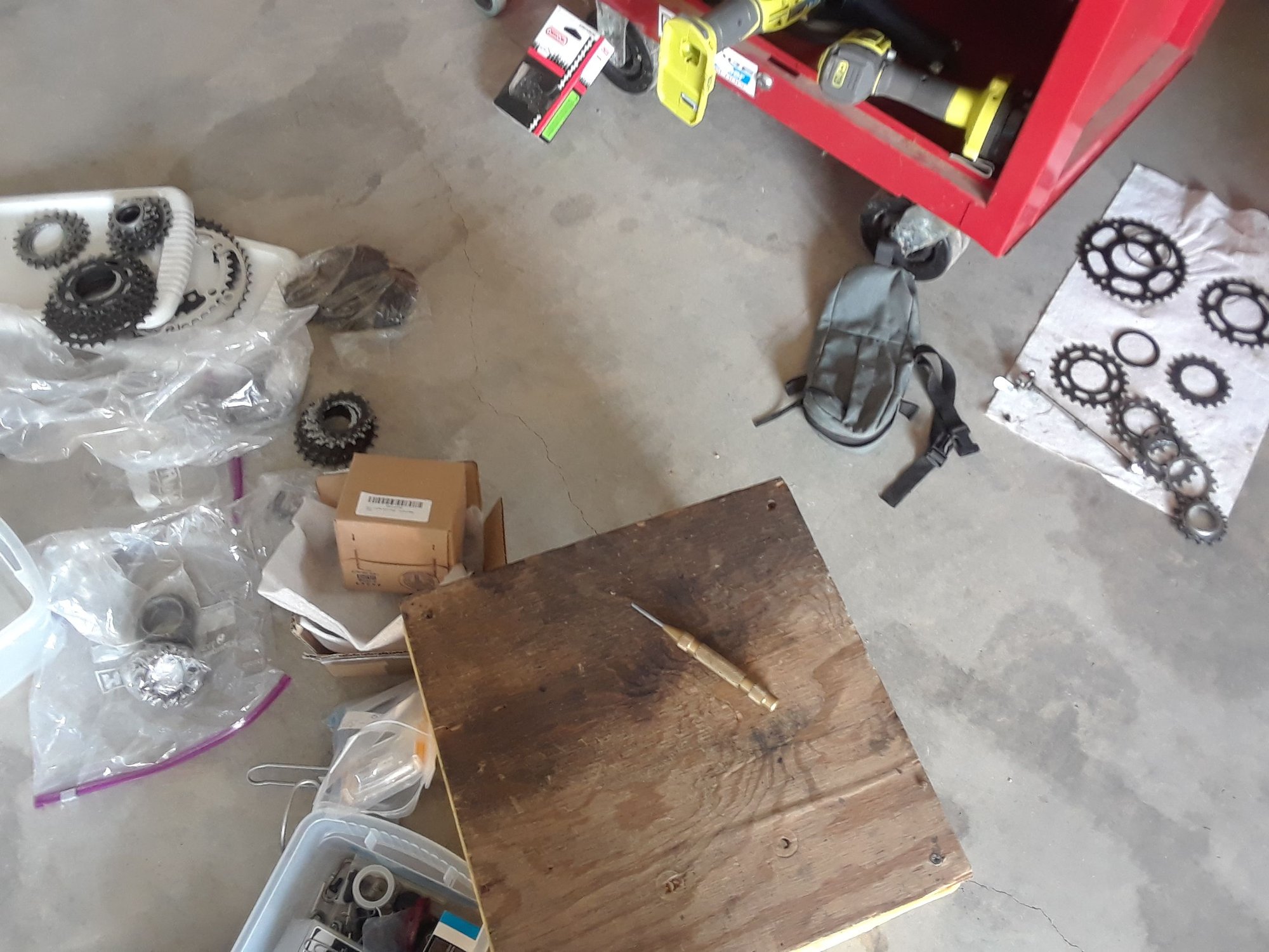
Now I feel pressure to make this work and not disappoint everyone.
Good questions that expose that I don’t know what I’m doing. Given the questions/skepticism from others, I finally threw the cogs on the hub to see how much room I have.
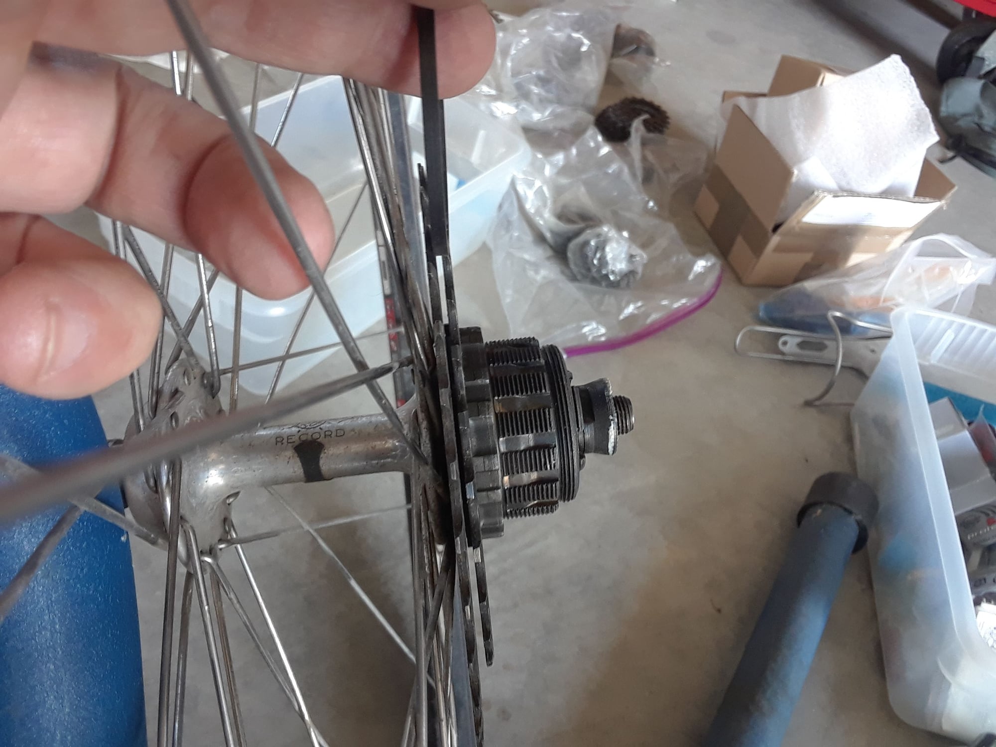
I don’t have as much room as I was imagining. The spacer is 2.7mm thick. With the 8th cog resting on the spokes, I eyeball about 1.3mm between the 8th and 7th cogs. I’m going to have to cut out the center of the 8th cog so I can move it medial (closer to the spokes) an additional 1.3mm.
I was thinking just a nut and bolt (my imagination is way off on actual dimensions). I don’t think there’s enough room for a bolt head (maybe an M4 allen head will work?) to clear the spokes. At least not M5. And a nut on the outside of the 7th cogs will interfere with the chain.
So tapping the 7th cog for an M4 bolt might work? With the M4 bolt head clearing the spokes? I'll have to see. The other option is welding the 8th and 7th cogs together.
Below is a 26t A-cog in the inner position as a baseline photo.
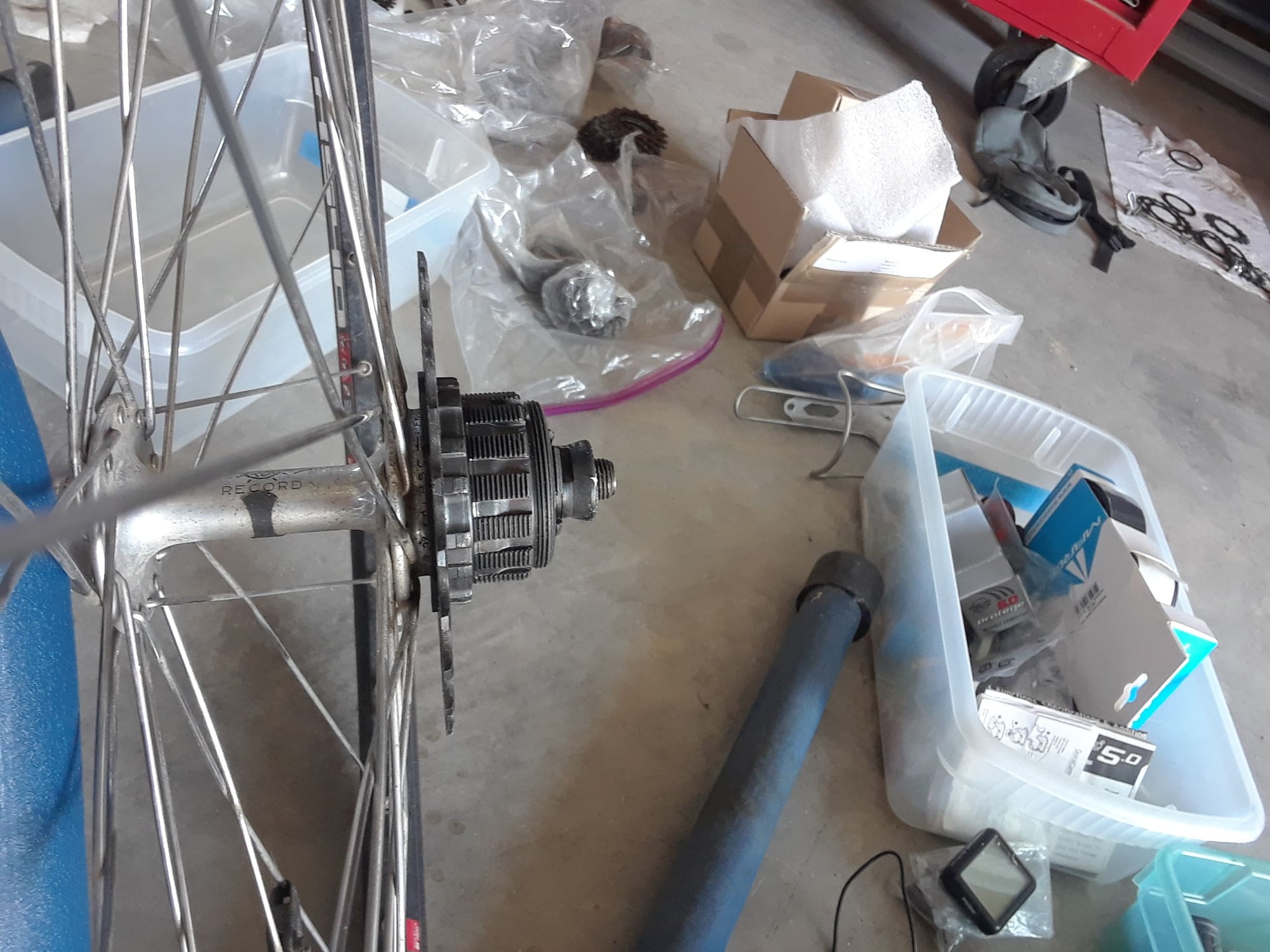
34t cog is in the proposed 8th position between the spokes and the freewheel. It's currently resting the spokes. The spacer I'm holding is 2.7mm so I need to move the 34t cog medial about 1 mm. I think cutting out the center of the 34t cog will allow moving it medial 1mm and clear the spokes. (I hope)
I’ll have to see how small those RivNuts/PlusNuts go. But if small enough, the heads may become too thin to work as a spacer. I'll have to look into the chainring bolts and spacers too. You’re full of good ideas. I really appreciate your suggestions.
Not sure about the determination. Though having posted this publicly may force me to see it through.
I don’t have the skills either. I did not know about martensite, austenite, annealing until I tried to drill the cog. I had thought heat treatment was only hardening. I've learned a little already.
I’m surprised at differences in forums; that you guys follow thread hijacking, on-topic rules. Please post your photos and tips from your project. I would think your photos and tips stay on topic as an aid to me.
I think I"m going to have to learn about heat treatment to restore the hardness as well. It turns out the few seconds of oxy/acet did affect the adjacent tooth. I can scratch it now. Better control of the oxy/acet and experimenting to find out the minimum heat needed would help too.
you are prepared to swap out individual Suntour Winner Pro cogs in order to get smaller tooth jumps between them. I may have to re-read your post where you talked about which gear inches that you have now, and what the progression of gear inches will be once the conversion is made.
I have never actually changed the individual cogs on my Suntour 7 speed freewheel. It would be nice if these were more like a cassette where the spline pattern is the same for every cog to be able to slide right on the freehub body. That design required far less intimate knowledge of which cog will fit into which stepped, splined, or threaded area on the freehub body. Could you talk about about how you will swap in different cogs in the middle of the freewheel?
For Winner Pro, it’s not as simple as a cassette but not too complicated. The 14t screws onto the body to lock the slide on cogs. The 13t screws onto the 14t. Those two are kinda fixed. There might be a 13t/12t combo? I don’t think there is a 15t option with a 14t screwing onto the 15t which would work better for my needs.
So you only have to deal with the two largest cogs (A cogs) which slide on with 4 splines. The middle cogs (B cogs) all slide on with multiple splines. Swapping the middle cogs is like the cassette.
Below is a blurry overview of my cog collection. Left upper is a stack of A cogs and a freewheel. To the right of those on the floor is a stack of B cogs. Threaded small locking cogs, spacers, old freewheel bodies are in the plastic bags. On the right on the paper towel is my current freewheel cogs and spacers.
So I guess I would like to know about the attachment of cog #8 to cog #7 . Now that you have softened the metal to make it drillable, what was your intention from there? Were you going to use chainring bolts and spacers through a through hole that is unthreaded or were you going to tap the through holes for a metric (or SAE) bolt and just go with a straight bolt and spacer set up?
I don’t have as much room as I was imagining. The spacer is 2.7mm thick. With the 8th cog resting on the spokes, I eyeball about 1.3mm between the 8th and 7th cogs. I’m going to have to cut out the center of the 8th cog so I can move it medial (closer to the spokes) an additional 1.3mm.
I was thinking just a nut and bolt (my imagination is way off on actual dimensions). I don’t think there’s enough room for a bolt head (maybe an M4 allen head will work?) to clear the spokes. At least not M5. And a nut on the outside of the 7th cogs will interfere with the chain.
So tapping the 7th cog for an M4 bolt might work? With the M4 bolt head clearing the spokes? I'll have to see. The other option is welding the 8th and 7th cogs together.
Below is a 26t A-cog in the inner position as a baseline photo.
34t cog is in the proposed 8th position between the spokes and the freewheel. It's currently resting the spokes. The spacer I'm holding is 2.7mm so I need to move the 34t cog medial about 1 mm. I think cutting out the center of the 34t cog will allow moving it medial 1mm and clear the spokes. (I hope)
I’m surprised at differences in forums; that you guys follow thread hijacking, on-topic rules. Please post your photos and tips from your project. I would think your photos and tips stay on topic as an aid to me.
I think I"m going to have to learn about heat treatment to restore the hardness as well. It turns out the few seconds of oxy/acet did affect the adjacent tooth. I can scratch it now. Better control of the oxy/acet and experimenting to find out the minimum heat needed would help too.
Last edited by Eiko; 08-14-19 at 01:23 PM.
08-14-19, 02:03 PM
#36
Senior Member

Join Date: Sep 2011
Location: Baltimore MD
Posts: 3,330
Bikes: '72 Motobecane Grand Record, '72 Gitane tandem, '72 Raleigh Super Course, '73 Raleigh Gran Sport, '73 Colnago Super, '76 Fiorelli Coppi, '78 Raleigh SBDU Team Pro, '78 Trek 930, '81 Holdsworth Special 650B, '86 Masi GC, ’94 Bridgestone RB-T
Mentioned: 67 Post(s)
Tagged: 0 Thread(s)
Quoted: 786 Post(s)
Liked 516 Times
in
280 Posts
I applaud your attempt. Good luck and god speed.
T'were me, I'd just drop the 13, and make a 7-speed: 14-15-17-19-22-26-34. Bump the big ring to 53 if you really need that tall a top gear.
T'were me, I'd just drop the 13, and make a 7-speed: 14-15-17-19-22-26-34. Bump the big ring to 53 if you really need that tall a top gear.
__________________
The man who dies with the most toys�is dead. - Rootboy
The man who dies with the most toys�is dead. - Rootboy
08-14-19, 04:42 PM
#37
Senior Member
Join Date: Oct 2005
Location: SW Ohio
Posts: 3,681
Bikes: Puch Marco Polo, Saint Tropez, Masi Gran Criterium
Mentioned: 25 Post(s)
Tagged: 0 Thread(s)
Quoted: 1163 Post(s)
Liked 441 Times
in
314 Posts
There are thin washers that you can slide over the freewheel hub threads to move the freewheel outboard. It appears from the of the winner pro freewheel body that there might be some room left on the dropout side to move the freewheel out a few mm with the spacer. This could potentially make it to where the correct spacer could be used between cogs 7 and 8 and hopefully still clear the spokes too.
08-14-19, 05:13 PM
#38
Senior Member
I remember reading that an 8-speed freewheel can be fit into 126 mm dropouts by moving axle spacers from NDS to DS and redishing.
08-14-19, 08:53 PM
#39
Member
Thread Starter
There are thin washers that you can slide over the freewheel hub threads to move the freewheel outboard. It appears from the of the winner pro freewheel body that there might be some room left on the dropout side to move the freewheel out a few mm with the spacer. This could potentially make it to where the correct spacer could be used between cogs 7 and 8 and hopefully still clear the spokes too.
I'm going to have to put this project on hold for now. I need to work on a Transit van for a trip to Chicago in a month. I'll post a new thread of progress (I'm assuming there will be) in a few months. Thank you all for your excellent ideas. You guys have really helped overcome a few little hurdles.
08-15-19, 07:12 PM
#40
Used to be Conspiratemus
Join Date: Jan 2009
Location: Hamilton ON Canada
Posts: 1,512
Mentioned: 4 Post(s)
Tagged: 0 Thread(s)
Quoted: 297 Post(s)
Liked 245 Times
in
163 Posts
...
I don�t have the skills either. I did not know about martensite, austenite, annealing until I tried to drill the cog. I had thought heat treatment was only hardening. I've learned a little already.
I�m surprised at differences in forums; that you guys follow thread hijacking, on-topic rules. Please post your photos and tips from your project. I would think your photos and tips stay on topic as an aid to me.
...
Likes For conspiratemus1:
08-16-19, 07:54 PM
#41
Used to be Conspiratemus
Join Date: Jan 2009
Location: Hamilton ON Canada
Posts: 1,512
Mentioned: 4 Post(s)
Tagged: 0 Thread(s)
Quoted: 297 Post(s)
Liked 245 Times
in
163 Posts
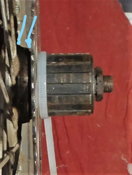
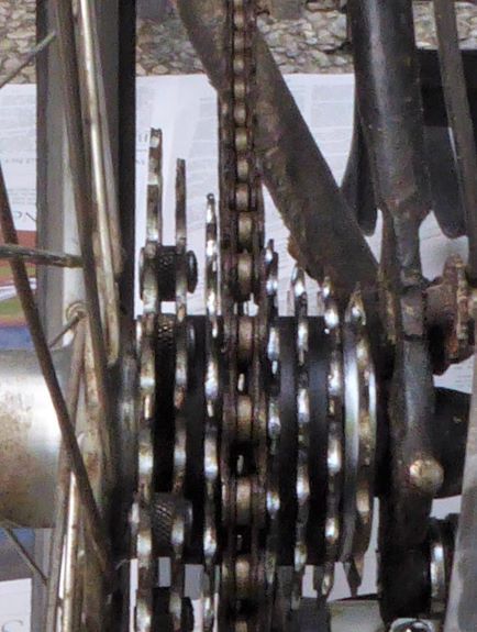
Hope this isn't a day late and a dollar short. My project was to mount an eighth sprocket onto the inside of the cassette of a Shimano FH-07 tandem hub from the 1990s. The hub is peculiar in that the DS shell has a prominent shoulder that steps the #1 cog too far out, making the hub wider and more asymmetric than it needs to be (always an issue on tandems.) What follows is a reconstruction of what I did a couple of years ago. The first three photos show the baseline situation.
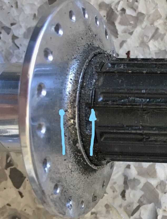
Not mine. Photo taken from an eBay auction.
Blue lollipop: root of shell shoulder
Blue arrow: stop on which dog of sprocket seats
----------------------------------------------------------------------------------------------------------------------
Sprocket placed against cassette body seat.
Lollipop and arrow same as previous photo. Note large space between sprocket and spokes...
----------------------------------------------------------------------------------------------------------------
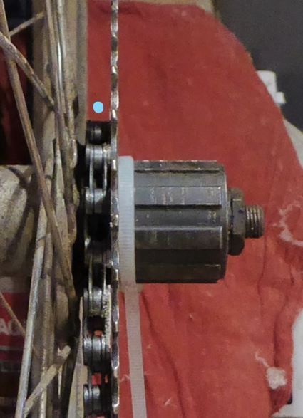
...into which an 8-speed chain will drop and run freely on the hub shell without jamming in spokes. Blue dot shows the gap.
------------------------------------------------------------------------------------------------------------------------------------------------------
The tandem(s) have graduated into other wheels and I wanted to use the hub for an all-rounder bad-weather utilitarian single bike, an old Jeunet from 1975. The cassette I had was a 7-speed Hyperglide with 23-tooth largest sprocket. I wanted to "fill in" that "blue-dot" space with a 26-tooth sprocket and, in so doing, make the cassette into an 8-speed. I decided to try to bolt a 26-tooth freewheel sprocket to the inside of the 23-tooth sprocket of the cassette. The "bore" of the freewheel sprocket is, of course, larger than that of the cassette, and it does not mate in any way with the splines of the cassette body. It will be supported only by bolts to the 23-tooth native sprocket and will "hang" into the "blue-dot" space. I wouldn't want to rig a tandem hub this way for fear that the force of two of us pushing in low gear up a hill would shear the bolts off. I wasn't even sure it would be safe for just me, but it has been. Because this was to be a friction-shifting setup, I wasn't worried about precise spacing between the sprockets, just wanted it all to fit in the space available.
First, I prepared my parts. The hub axle was shortened to make 130 mm OLD (the tandem spacing was 140mm). The cassette was disassembled into loose cogs by removing those 3 long thin hex screws that align the sprockets.
I had to hunt around to find a suitable freewheel sprocket to use as the new #1 . Good sprockets are very hard to drill. Since this was, at the time, more proof of concept than anything else, I settled on a cheap sprocket salvaged from a knock-off Shimanoid freewheel that proved not too hard to drill with a cobalt bit. The cassette cog was suprisingly easy to drill. The next photos show how it went together.

Top side of assembled sprocket pair
Blue Arrow: cleaned-up bolt location to show countersinking and grinding down the bolt head to avoid fouling chain.
White circle: visible edge of stem-nut spacer
-------------------------------------------------------------------------------------------------------------------------------------------------

Bottom side. Note winter corrosion x 2. White dots in both photos show the visual checks for alignment.
--------------------------------------------------------------------------------------------------------------------------------
The crucial dimensions to check are that the bolt heads in the #2 sprocket do not foul the chain when it's trying to settle onto the #3 sprocket, which of course is not seen in the photo, nor do they foul the chain when it's on the #2 sprocket. The chain links reach down the face of the sprocket a surprisingly long way and there is a very small window where the bolts can be placed. Ideally I would have used flat-head bolts to be sure they were flush with the sprocket face but I had to use oval-heads that were available in the size I wanted. I think they are #8-32 but they could be #6 , or ?M4, don't remember and didn't think to look closely when I had the cassette apart to take these pix. Too big and I'd have to drill away too much metal on the webs of the sprockets.
The two sprockets wanted to be as closely concentric as possible and the bolt holes had to be positioned where a reasonable amount of metal was available in both. I lined them up visually so that the six apertures indicated by the white dots were the same size -- that was more accurate than trying to true up the inner diameters by eye. I clamped them together against a board and drilled away, same size hole all the way through the two, since I wasn't cutting threads in the lower one. Then I countersunk the holes in the upper sprocket to receive the oval heads. After de-burring I inserted a Presta valve-stem nut between the sprockets at each hole to act as a spacer, then bolted the two together. After the threadlocker set I ground down the protruding ends of the bolts, and also ground down the heads just a little, as it turned out.
It would have been nice to tap threads into the bottom sprocket and not need nuts, because I knew they'd create a clearance problem. But the sprocket was only 1.7 mm thick, less than 3 threads of an M4 x 0.7 bolt (or whatever size I actually used.) I never thought of using Rivnuts until @masi61 mentioned it here -- I'd never actually seen one in fact. Now that I know about them, they seem like such an ideal solution that I'm going to learn how to use them and redo this cassette.
Moment of Truth:
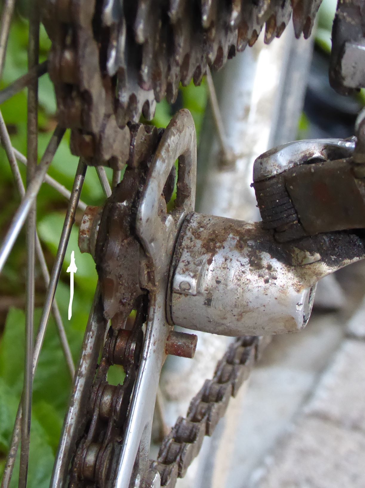
The next photos show the cassette installed, with critical clearance points identified. Unfortunately, the nuts fouled the spokes upon test fitting. So I placed a 1.5 mm spacer between the cassette and the freehub stops and this time it passed, as in the first photo.
Cassette installed with spacer against hub (not visible; see text)
Blue arrow: Nut just clears spokes
White arrows: No visible protrusion of bolt heads (view is not quite close enough to perpendicular to prove this)
White arrowhead: valve-stem nut spacer.
---------------------------------------------------------------------------------------------------------------------------------------------------
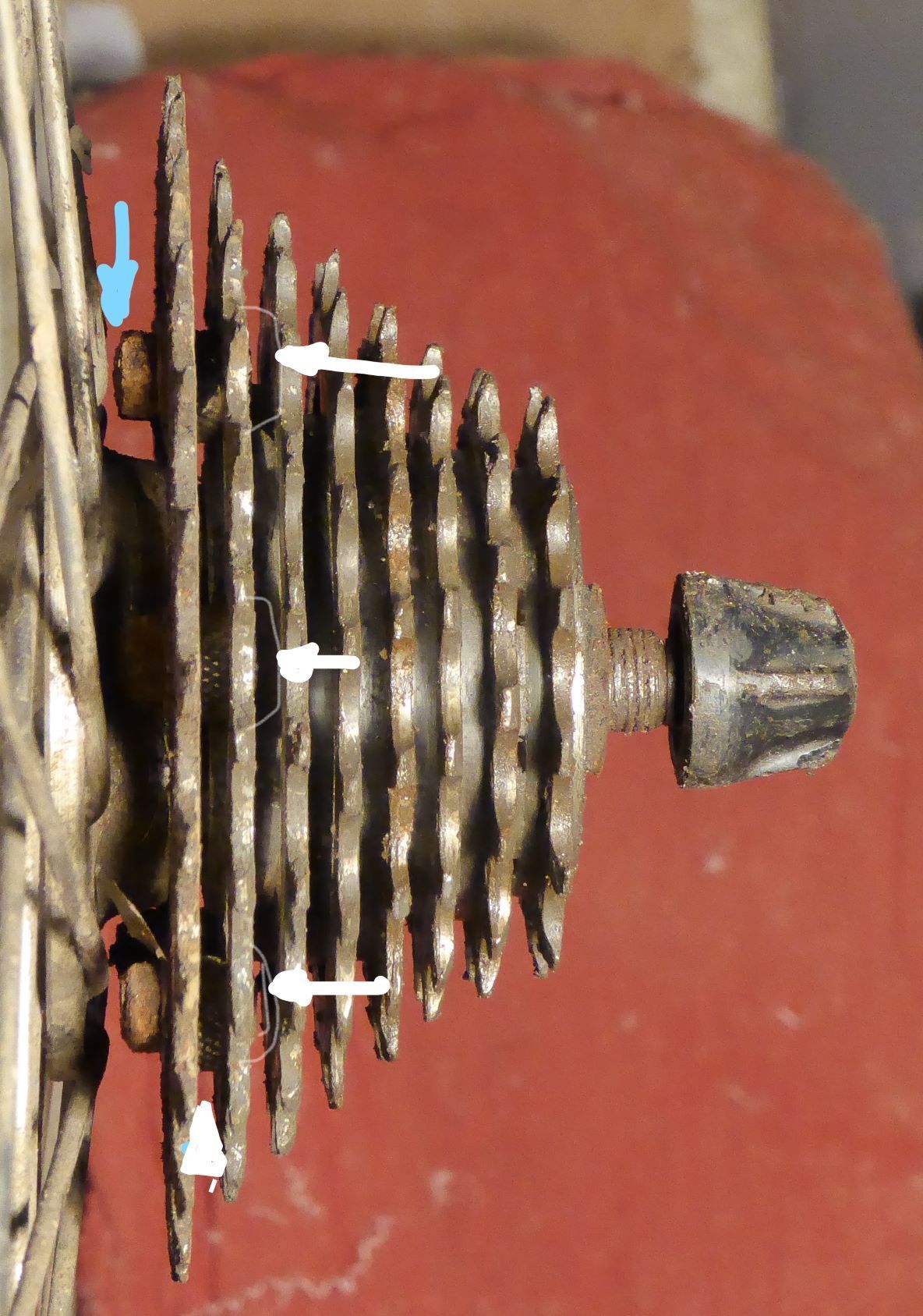
With the wheel installed, the chain shifted smoothly over all 8 sprockets (still does today even though very dirty, sorry!) Even though this old derailer's jockey pulley has a nut on the inner side of the cage, there is still lots of room. The limiting clearance is the nuts on back of the cassette. I'm really eager to try Rivnuts here. The centering of the rim on the wheel has not changed -- the only adjustment was to the low-gear limiting screw of the derailer so it could reach the new #1 .
Derailer with chain on #1 sprocket.
White arrow: Jockey pulley nut clears spokes easily.
--------------------------------------------------------------------------------------------------------------------------------------------
Bottom line: It worked. Because I had an exceptionally large gap between cassette and spokes to work with, I was optimistic that I'd have room to do this even resorting to using nuts on the back side (and I still needed a spacer, though -- those nuts take up a lot of space.) For more normal situations, I think you'd need some sort of near-flush mounting method, like Rivnuts, building up the thickness of the sprocket (by welding a ring of steel at the bolt holes?) enough to tap three or four threads into it, or by welding the new sprocket directly to the native sprocket of the cassette, with suitable spacers. I would like to be able to not use the spacer under the cassette because the 1.5 mm outward it pushes the cassette leaves that much less for the lockring to screw into. I might have some room to grind a little more off each nut without weakening it too much. Finally, it's a cheap sprocket but I don't need to use it very much and it's not likely to wear out before I do.
Anyway, I hope @Eiko is able to come back to his project. These things are fun to do, don't damage "heirloom" equipment, and learn ya some new skills and problem-solving, important for us retired people.
Not mine. Photo taken from an eBay auction.
Blue lollipop: root of shell shoulder
Blue arrow: stop on which dog of sprocket seats
----------------------------------------------------------------------------------------------------------------------
Sprocket placed against cassette body seat.
Lollipop and arrow same as previous photo. Note large space between sprocket and spokes...
----------------------------------------------------------------------------------------------------------------
...into which an 8-speed chain will drop and run freely on the hub shell without jamming in spokes. Blue dot shows the gap.
------------------------------------------------------------------------------------------------------------------------------------------------------
The tandem(s) have graduated into other wheels and I wanted to use the hub for an all-rounder bad-weather utilitarian single bike, an old Jeunet from 1975. The cassette I had was a 7-speed Hyperglide with 23-tooth largest sprocket. I wanted to "fill in" that "blue-dot" space with a 26-tooth sprocket and, in so doing, make the cassette into an 8-speed. I decided to try to bolt a 26-tooth freewheel sprocket to the inside of the 23-tooth sprocket of the cassette. The "bore" of the freewheel sprocket is, of course, larger than that of the cassette, and it does not mate in any way with the splines of the cassette body. It will be supported only by bolts to the 23-tooth native sprocket and will "hang" into the "blue-dot" space. I wouldn't want to rig a tandem hub this way for fear that the force of two of us pushing in low gear up a hill would shear the bolts off. I wasn't even sure it would be safe for just me, but it has been. Because this was to be a friction-shifting setup, I wasn't worried about precise spacing between the sprockets, just wanted it all to fit in the space available.
First, I prepared my parts. The hub axle was shortened to make 130 mm OLD (the tandem spacing was 140mm). The cassette was disassembled into loose cogs by removing those 3 long thin hex screws that align the sprockets.
I had to hunt around to find a suitable freewheel sprocket to use as the new #1 . Good sprockets are very hard to drill. Since this was, at the time, more proof of concept than anything else, I settled on a cheap sprocket salvaged from a knock-off Shimanoid freewheel that proved not too hard to drill with a cobalt bit. The cassette cog was suprisingly easy to drill. The next photos show how it went together.
Top side of assembled sprocket pair
Blue Arrow: cleaned-up bolt location to show countersinking and grinding down the bolt head to avoid fouling chain.
White circle: visible edge of stem-nut spacer
-------------------------------------------------------------------------------------------------------------------------------------------------
Bottom side. Note winter corrosion x 2. White dots in both photos show the visual checks for alignment.
--------------------------------------------------------------------------------------------------------------------------------
The crucial dimensions to check are that the bolt heads in the #2 sprocket do not foul the chain when it's trying to settle onto the #3 sprocket, which of course is not seen in the photo, nor do they foul the chain when it's on the #2 sprocket. The chain links reach down the face of the sprocket a surprisingly long way and there is a very small window where the bolts can be placed. Ideally I would have used flat-head bolts to be sure they were flush with the sprocket face but I had to use oval-heads that were available in the size I wanted. I think they are #8-32 but they could be #6 , or ?M4, don't remember and didn't think to look closely when I had the cassette apart to take these pix. Too big and I'd have to drill away too much metal on the webs of the sprockets.
The two sprockets wanted to be as closely concentric as possible and the bolt holes had to be positioned where a reasonable amount of metal was available in both. I lined them up visually so that the six apertures indicated by the white dots were the same size -- that was more accurate than trying to true up the inner diameters by eye. I clamped them together against a board and drilled away, same size hole all the way through the two, since I wasn't cutting threads in the lower one. Then I countersunk the holes in the upper sprocket to receive the oval heads. After de-burring I inserted a Presta valve-stem nut between the sprockets at each hole to act as a spacer, then bolted the two together. After the threadlocker set I ground down the protruding ends of the bolts, and also ground down the heads just a little, as it turned out.
It would have been nice to tap threads into the bottom sprocket and not need nuts, because I knew they'd create a clearance problem. But the sprocket was only 1.7 mm thick, less than 3 threads of an M4 x 0.7 bolt (or whatever size I actually used.) I never thought of using Rivnuts until @masi61 mentioned it here -- I'd never actually seen one in fact. Now that I know about them, they seem like such an ideal solution that I'm going to learn how to use them and redo this cassette.
Moment of Truth:
The next photos show the cassette installed, with critical clearance points identified. Unfortunately, the nuts fouled the spokes upon test fitting. So I placed a 1.5 mm spacer between the cassette and the freehub stops and this time it passed, as in the first photo.
Cassette installed with spacer against hub (not visible; see text)
Blue arrow: Nut just clears spokes
White arrows: No visible protrusion of bolt heads (view is not quite close enough to perpendicular to prove this)
White arrowhead: valve-stem nut spacer.
---------------------------------------------------------------------------------------------------------------------------------------------------
With the wheel installed, the chain shifted smoothly over all 8 sprockets (still does today even though very dirty, sorry!) Even though this old derailer's jockey pulley has a nut on the inner side of the cage, there is still lots of room. The limiting clearance is the nuts on back of the cassette. I'm really eager to try Rivnuts here. The centering of the rim on the wheel has not changed -- the only adjustment was to the low-gear limiting screw of the derailer so it could reach the new #1 .
Derailer with chain on #1 sprocket.
White arrow: Jockey pulley nut clears spokes easily.
--------------------------------------------------------------------------------------------------------------------------------------------
Bottom line: It worked. Because I had an exceptionally large gap between cassette and spokes to work with, I was optimistic that I'd have room to do this even resorting to using nuts on the back side (and I still needed a spacer, though -- those nuts take up a lot of space.) For more normal situations, I think you'd need some sort of near-flush mounting method, like Rivnuts, building up the thickness of the sprocket (by welding a ring of steel at the bolt holes?) enough to tap three or four threads into it, or by welding the new sprocket directly to the native sprocket of the cassette, with suitable spacers. I would like to be able to not use the spacer under the cassette because the 1.5 mm outward it pushes the cassette leaves that much less for the lockring to screw into. I might have some room to grind a little more off each nut without weakening it too much. Finally, it's a cheap sprocket but I don't need to use it very much and it's not likely to wear out before I do.
Anyway, I hope @Eiko is able to come back to his project. These things are fun to do, don't damage "heirloom" equipment, and learn ya some new skills and problem-solving, important for us retired people.
Last edited by conspiratemus1; 08-16-19 at 09:03 PM. Reason: The added sprocket is 26t, not 25.
08-16-19, 08:16 PM
#42
Senior Member
Join Date: Oct 2011
Location: Fairplay Co
Posts: 9,512
Bikes: Current 79 Nishiki Custum Sport, Jeunet 620, notable previous bikes P.K. Ripper loop tail, Kawahara Laser Lite, Paramount Track full chrome, Raliegh Internatioanl, Motobecan Super Mirage. 59 Crown royak 3 speed
Mentioned: 26 Post(s)
Tagged: 1 Thread(s)
Quoted: 789 Post(s)
Liked 1,736 Times
in
629 Posts
I have DA cassete 6/7 speed running with a Suntour shift group and the clearences are supper close had to add a spacer and dish the wheel slightly to get eveything to work nice, You will need to add 1.5mm spacing to the drive side and maybe dish the wheel plus realigne the RD hanger to get stuff to work nices.
08-17-19, 08:40 PM
#43
Member
Thread Starter
Your comment summarizes my feelings - I initially wanted to 'improve' the bike. Now the challenges and problem solving as well as the learning and new skills are more interesting than the result.
"The hub is peculiar in that the DS shell has a prominent shoulder that steps the #1 cog too far out, making the hub wider and more asymmetric than it needs to be" Weird. You have a lot more space than I do.
I kinda wish you had to deal with hardened steel cogs to see what solution you would have come up with. But I'm taking away that maybe I don't need to re-harden the teeth that will get unhardened and the spiders that will be bolted together. And that M4 bolts will work. M4 looked a bit too small by my non-machinist/non-metallurgical eye.
What did you use to enlarge the center hole of the new cog? I'm considering a large hole saw.
Good point that the cog is too thin for tapping. I'm now considering a quick weld on the end of the bolt in the cog instead of a nut. Or brazing (which would be a new skill for me).
A Rivnut may provide the nut function as well as the spacer function. I'd assume the length of the Rivnut would have to be ground down to provide the correct spacer size.
You might be able to grind down the nuts by 1.5 mm? There shouldn't be too much axial load on the nuts and the smaller number of nut threads should be able to handle that small force?
"For more normal situations, I think you'd need some sort of near-flush mounting method, like Rivnuts, building up the thickness of the sprocket (by welding a ring of steel at the bolt holes?) enough to tap three or four threads into it, or by welding the new sprocket directly to the native sprocket of the cassette, with suitable spacers." I would generally like to try non-permanent solutions like the bolts/nuts/Rivnuts before resorting to soldering/welding.
As mentioned, I'll have to come back to this project in a couple of months.
I have DA cassete 6/7 speed running with a Suntour shift group and the clearences are supper close had to add a spacer and dish the wheel slightly to get eveything to work nice, You will need to add 1.5mm spacing to the drive side and maybe dish the wheel plus realigne the RD hanger to get stuff to work nices.
Last edited by Eiko; 08-17-19 at 08:59 PM.
08-17-19, 11:01 PM
#44
Used to be Conspiratemus
Join Date: Jan 2009
Location: Hamilton ON Canada
Posts: 1,512
Mentioned: 4 Post(s)
Tagged: 0 Thread(s)
Quoted: 297 Post(s)
Liked 245 Times
in
163 Posts
Hi @Eiko, glad you enjoyed my efforts.
Quotes from you in blue:
...Use of the valve stem nut - but I measure one of those at 3.0 mm thick. Does that match your cog spacing? ...
Close enough. The spacing of the native HyperGlide 7-sp sprockets is 3.15 mm, just a bit more than the stem nut.
...I kinda wish you had to deal with hardened steel cogs to see what solution you would have come up with. Ha. I'm glad I didn't....but see below.*
And that M4 bolts will work. M4 looked a bit too small... You're right, they are indeed M4. I must have been worried about that, too, since I now realize that I drilled the 23T "host" sprocket to take M5 bolts. I think I went with M4 for 2 reasons: On Shimano's high-end 9-speed cassettes, the little rivets that fix the large sprockets onto the central carrier are about the size of M4. There are 6 of them and they are the only things transmitting pedaling force from the sprocket into the hub. Just as in my bash-up, there is no direct splined connection between sprocket and hub. The other reason was than M4 has a thread pitch of 0.7 mm, so you get 3 threads engaged with a thinner nut than you do with M5, with pitch of 0.8 mm. But again, see below.*
What did you use to enlarge the center hole of the new cog? I'm considering a large hole saw.
The large hole in the new ("graft") cog is just how it comes from the factory, jagged teeth (engagement splines, actually) and all. Remember cassette bodies are much smaller than freewheel bodies, especially close to the hub. That's one of the things that made this cassette-based project easier than modifying a freewheel -- there's a nice extra clear space in the middle of the freewheel sprocket.
...You might be able to grind down the nuts by 1.5 mm? There shouldn't be too much axial load on the nuts and the smaller number of nut threads should be able to handle that small force?
My "do-as-I'm-told-because-I-don't-know-enough-to-break-the-rules" rule is 3 threads when it's steel into steel, to ensure the nut will tolerate the tension from the initial torquing of the fastener, never mind the stress it experiences in use. The M4 nuts are less than 3 mm thick as it is. But yet again, see below.*
"For more normal situations, I think you'd need some sort of near-flush mounting method, like Rivnuts,..."
which leads to the re-think, below*:
* I realize I erred in worrying about the chain fouling on the fastener heads on outer face of the the 23T sprocket when it shifts out to the next smaller. That won't happen because they are mounted low enough (close enough to centre) that the chain never gets near them -- they are hiding deep in the valley between the two sprockets. You do have to make sure the fasteners don't foul the chain when it is engaged on the 23T. But the only other clearance test the fastener has to pass it that it isn't thicker than the inter-sprocket spacing, in this case 3.15 mm, which would prevent the next smaller sprocket from seating.
Therefore....there is no need for the M4 nuts to be located on the back side of the two-sprocket sandwich after all. I could flip the nuts and bolts around so that the bolt head is on the back and the nut is on the face side. Then, with countersunk holes in the back side of the "graft" sprocket, I would have little (with oval-head bolts) or no (with flat-head bolts) protrusion on the back side. This would be useful to your project where you have less space to the spokes. It would avoid having to grind down Rivnuts to match the sprocket spacing. Downside is that while I was able to drill the holes in both sprockets with cobalt twist bits, my countersink bits are just high-speed steel for wood and aluminum. One clearly must have worked OK for the holes in the 23T, but this steel was softer than the grafted freewheel sprocket and cobalt countersink bits are spendy.
Something to sleep on.
Quotes from you in blue:
...Use of the valve stem nut - but I measure one of those at 3.0 mm thick. Does that match your cog spacing? ...
Close enough. The spacing of the native HyperGlide 7-sp sprockets is 3.15 mm, just a bit more than the stem nut.
...I kinda wish you had to deal with hardened steel cogs to see what solution you would have come up with. Ha. I'm glad I didn't....but see below.*
And that M4 bolts will work. M4 looked a bit too small... You're right, they are indeed M4. I must have been worried about that, too, since I now realize that I drilled the 23T "host" sprocket to take M5 bolts.
I think I went with M4 for 2 reasons: On Shimano's high-end 9-speed cassettes, the little rivets that fix the large sprockets onto the central carrier are about the size of M4. There are 6 of them and they are the only things transmitting pedaling force from the sprocket into the hub. Just as in my bash-up, there is no direct splined connection between sprocket and hub. The other reason was than M4 has a thread pitch of 0.7 mm, so you get 3 threads engaged with a thinner nut than you do with M5, with pitch of 0.8 mm. But again, see below.*What did you use to enlarge the center hole of the new cog? I'm considering a large hole saw.
The large hole in the new ("graft") cog is just how it comes from the factory, jagged teeth (engagement splines, actually) and all. Remember cassette bodies are much smaller than freewheel bodies, especially close to the hub. That's one of the things that made this cassette-based project easier than modifying a freewheel -- there's a nice extra clear space in the middle of the freewheel sprocket.
...You might be able to grind down the nuts by 1.5 mm? There shouldn't be too much axial load on the nuts and the smaller number of nut threads should be able to handle that small force?
My "do-as-I'm-told-because-I-don't-know-enough-to-break-the-rules" rule is 3 threads when it's steel into steel, to ensure the nut will tolerate the tension from the initial torquing of the fastener, never mind the stress it experiences in use. The M4 nuts are less than 3 mm thick as it is. But yet again, see below.*
"For more normal situations, I think you'd need some sort of near-flush mounting method, like Rivnuts,..."
which leads to the re-think, below*:
* I realize I erred in worrying about the chain fouling on the fastener heads on outer face of the the 23T sprocket when it shifts out to the next smaller. That won't happen because they are mounted low enough (close enough to centre) that the chain never gets near them -- they are hiding deep in the valley between the two sprockets. You do have to make sure the fasteners don't foul the chain when it is engaged on the 23T. But the only other clearance test the fastener has to pass it that it isn't thicker than the inter-sprocket spacing, in this case 3.15 mm, which would prevent the next smaller sprocket from seating.
Therefore....there is no need for the M4 nuts to be located on the back side of the two-sprocket sandwich after all. I could flip the nuts and bolts around so that the bolt head is on the back and the nut is on the face side. Then, with countersunk holes in the back side of the "graft" sprocket, I would have little (with oval-head bolts) or no (with flat-head bolts) protrusion on the back side. This would be useful to your project where you have less space to the spokes. It would avoid having to grind down Rivnuts to match the sprocket spacing. Downside is that while I was able to drill the holes in both sprockets with cobalt twist bits, my countersink bits are just high-speed steel for wood and aluminum. One clearly must have worked OK for the holes in the 23T, but this steel was softer than the grafted freewheel sprocket and cobalt countersink bits are spendy.
Something to sleep on.
Last edited by conspiratemus1; 08-17-19 at 11:05 PM.
08-18-19, 09:25 AM
#45
Member
Thread Starter
[QUOTE=conspiratemus1;21080310]Good idea about using blue to highlight quotes.
My "do-as-I'm-told-because-I-don't-know-enough-to-break-the-rules" rule is 3 threads when it's steel into steel, to ensure the nut will tolerate the tension from the initial torquing of the fastener, never mind the stress it experiences in use. The M4 nuts are less than 3 mm thick as it is.
My friend tells me that "something like 80% of the force will be on the first two threads". And I don't think the bolt and nut will be exposed to a lot of lateral force compared to the inline force from the chain (whatever direction that force is - longitudinal?). The lateral force would be from the position as the 1st cog (is that the standard nomenclature? Most medial/closest to the spokes is 1 and the outer cog is 8?) and resulting chain deflection.
The 3 thread rule is something else I learned from you. If you're not a machinist, that sounds like something you picked up from the EAA. This discussion probably won't matter since I'm leaning to the Rivnut. Because of the small lateral force from the chain, I think my thought of using the Rivnut as a spacer won't work. The cog needs to be tightly held in place with an actual spacer. My friend suggests silver soldering the cog to the Rivnut would probably hold the cog in place without an additional spacer.
I'll have to go measure the M4 nut to see if that can be a spacer.
The large hole in the new ("graft") cog is just how it comes from the factory, jagged teeth (engagement splines, actually) and all. I didn't think you made the cuts - they are slanted and I figured you would have made them square. But they also looked to small to be engagement splines.
Remember cassette bodies are much smaller than freewheel bodies, especially close to the hub. That's one of the things that made this cassette-based project easier than modifying a freewheel Not fair! Same for the next point.
You do have to make sure the fasteners don't foul the chain when it is engaged on the 23T. But the only other clearance test the fastener has to pass it that it isn't thicker than the inter-sprocket spacing, in this case 3.15 mm, which would prevent the next smaller sprocket from seating. A bolt head or nut would be on my 2nd cog (26t). And then the jump to 22t exposes the bolt or nut to the chain. My bolt needs to be further from the center than yours (in addition to the larger dia of the freewheel vs cassette) to clear the spokes. Although the Rivnut may alleviate that issue. Or I could use a very thin spacer between the hub and freewheel to gain a bit of clearance at the spokes - similar to what you did.
I was able to drill the holes in both sprockets with cobalt twist bits, my countersink bits are just high-speed steel for wood and aluminum. One clearly must have worked OK for the holes in the 23T, but this steel was softer than the grafted freewheel sprocket and cobalt countersink bits are spendy. The 23T Shimano was softer than the generic freewheel sprocket? Surprised. I did find that removal of the hardening made the cog easy to drill with a cobalt bit. I assume it'd be easy to countersink and cut too at this point, maybe even with HSS.
Consolidating all these thoughts and advice, at this point I'm thinking Rivnuts on the inside of the 1st cog, a spacer (go measure the thickness of an M4 nut), and then a countersunk flat head bolt on the outside of cog 2.
Last edited by Eiko; 08-18-19 at 04:06 PM.
08-18-19, 09:06 PM
#46
Used to be Conspiratemus
Join Date: Jan 2009
Location: Hamilton ON Canada
Posts: 1,512
Mentioned: 4 Post(s)
Tagged: 0 Thread(s)
Quoted: 297 Post(s)
Liked 245 Times
in
163 Posts
@Eiko,
If you're not a machinist, ...
Channeling Bones McCoy: "I'm just a country doctor, not a machinist." (You can only guess how badly I've wanted to use that and how long I've had to wait! ... I'm retired.) You could imagine the misquoted "Dammit Jim,...." preface if you liked.
I didn't think you made the cuts - they are slanted and I figured you would have made them square. But they also looked to small to be engagement splines.
As I said, it's cheap. I would say it looked like it was made from eavestroughing material, ...but that would be an insult to the crew who just replaced ours. And believe me, I am quite capable of making clumsy jagged cuts...just not in people.
The 23T Shimano was softer than the generic freewheel sprocket? Surprised.
Yes, weird. You are right to be sceptical. Guess I should just try scratching one with the other and see. On the other hand, the late Mike Barry (Mariposa Bicycles) used to say that aluminum chainrings lasted longer than the steel ones that preceded them -- and he raced with both -- even though they are of course softer. Not sure I ever understood his reasoning and it's too late to ask him to elaborate now. But fair enough, what kills a sprocket is letting a worn chain ride on it, and old freewheels were notorious for getting hooked teeth even though hard steel. Whatever, my HSS countersink chewed right into the holes of that HyperGlide sprocket. Maybe the teeth are hardened more than the face -- is that possible? Or maybe the countersink is now just toast from abusing it in steel. I'm going to do some reading about this.
P.S.: An oval-head machine screw is much thinner, effectively, than a hex- or Allen- head because about 2/3 of its thickness is countersunk into the mounting hole, e.g., in the plastic covers over light switches and electrical outlets. They usually have a slot or Phillips drive and look like a flat-head screw with a bulging top. They look a little "dressier" than flat-heads.
Last edited by conspiratemus1; 08-19-19 at 02:45 PM.
08-25-19, 08:31 PM
#47
Member
Thread Starter
heheh...

Maybe the teeth are hardened more than the face -- is that possible?
Watch this gif: https://imgur.com/gallery/2mFdxNb/ From my single experience with a hardened steel sprocket, if anything below carbide went through, then it was not hardened steel. (hmm, learning weird site rules - links or even mentioning red _dit.com are not allowed)
Given your discussion on chainrings, rear sprockets, aluminum, steel, that your Shimano sprocket did not appear hardened, it may not be necessary for me to reharden the cogs after removing the hardening to work on them. I appreciate the tip on chain wear killing teeth.
Last edited by Eiko; 08-25-19 at 08:47 PM.
09-12-19, 07:30 PM
#48
Used to be Conspiratemus
Join Date: Jan 2009
Location: Hamilton ON Canada
Posts: 1,512
Mentioned: 4 Post(s)
Tagged: 0 Thread(s)
Quoted: 297 Post(s)
Liked 245 Times
in
163 Posts
Update on this project, for which @Eiko graciously allowed me to hijack his thread. We have been sharing notes and here is described the completed Mark II. It works....and doesn't look half bad. Completed photo first, those who are interested can read on following:
8 sprockets on 7-speed cassette
First, because this is going to be a keeper, not just proof of concept, I sprang for some new parts instead of rummaging through my junk bins:
NOS Hyperglide 7-speed cassette, 13-23 T
Barely used Maillard freewheel sprocket 26 teeth.
NOS Uniglide 23 tooth cassette sprocket (just because I stumbled on it while searching eBay and realized it would allow me to avoid drilling holes in the 23-tooth sprocket of my new cassette.)
Fasteners were the challenge and will get a full treatment in a subsequent separate post (#51). There might be easier ways of doing this but nothing else that was available to me in stainless steel and gave me the appearance and clearance I was aiming for.

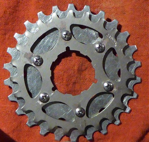
26T sprocket (cropped from seller's listing)

Uniglide 23T (cropped from seller's listing)
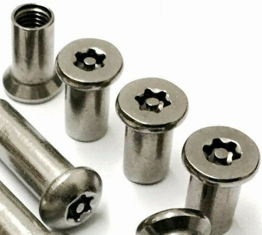
Countersunk sleeve nuts, as obtained. (cropped from seller's listing) See next post for explanation. Male halves are stainless steel machine screws. Spacers between sprockets will be Presta valve-stem nuts as before.
I prepared the fasteners first, (see post #51) before drilling holes, because I wasn't sure what I was going to end up with. The plan was to put male machine screws through small holes in the Uniglide sprocket and female sleeve nuts through larger holes in the freewheel sprocket. I'll explain the sizing later but what you see in the finished product are SAE 8-32 screws going into sleeve nuts that started out as blind-end M5 but were drilled out and tapped to 8-32.
First, as with the proof-of-concept version described earlier, I worked out where the holes could safely (or boldly?...) go without fouling the chain or leaving too little metal in the web of the Uniglide sprocket. The freewheel sprocket was thick and had lots of metal, so larger holes go in this piece. I was hoping that the lightening holes already drilled in the latter might serve for fastening but no such luck -- they're in the wrong place. I used a grinding bit in a cordless drill to scuff a divot into the surface hardening around the probable hole locations of both pieces, in order to be able to get a drill bit started. I scratched an index mark (with a file handle tip) at one hole location on both pieces to aid in alignment for later assembly. Because the holes were going to be drilled by eye, only one of six possible clock orientations would match up. I carefully aligned the two sprockets to get them as close to concentric as I could and, after verifying that a hole drilled through the upper would continue on in the right place through the lower, I clamped them to my backing board and to the workbench.
The scuffed Ultraglide sprocket accepted a centre punch with a solid whack. A good cobalt drill bit went right through it and started nicely into the freewheel sprocket below. I don't have a drill press so I used my old corded power drill, with the speed lock set slow enough to drill in steel without overheating. Lots of oil and heavy pressure applied vertically onto a low bench. Eye protection, leather gloves, proper shoes, and a shop apron. With six holes drilled into the Uniglide sprocket, I unclamped it and finished the larger holes through the freewheel sprocket, through which the female half of the sleeve nut will pass. The black oxide Dewalt bits from the set in the yellow box work very well as I didn't have a cobalt bit large enough. Again, slow speed, heavy pressure, lots of oil. Didn't see any smoke from any of the 12 holes and didn’t break any bits.
Next was to countersink the holes on the correct sides. Both sprockets were ever so slightly thinner than the countersunk portions of the fasteners that would seat into them. That meant that to countersink them completely, the far side of each hole would have to be larger than the shaft diameter of the screw or sleeve nut (as the case may be.) I didn't want to make the hole in the Uniglide sprocket any bigger than the screw, and I didn't want the shoulder of the sleeve nut poking through the freewheel sprocket where it might interfere with the seating of the spacers (which were already a snug fit over the sleeve nuts.) So I just countersunk (sank?) until there was a sharp edge on the far side of each hole, indicating that any further would start to enlarge the hole. That's why in the photos you can see that the fasteners aren't quite flush with the sprockets. (The oval heads are meant to bulge up above the surface, but there is more than just the oval that is proud if you look closely.) This was hard work. I've tried a variety of countersinks in steel and none are really satisfactory in a hand drill. Make sure you're countersinking the correct side of each sprocket!
Edit: The sleeve nuts have to be trimmed so that they don't protrude above the valve-nut spacers that slip on over them. Because of the less than perfect countersinking, it's impossible to predict this length precisely beforehand. So I cut them to rough length first, then filed and ground them down until flush with the spacers. Careful, because the valve nuts are softer than then the sleeve nuts. The idea was to leave as much thread as possible for the machine screws. See post #51.
That done, it was simple to bolt the pieces together, [Edit: trim off the excess length of the machine screws], reassemble the cassette, and Voil�, 8 speeds on 7. I also swapped out the old rear derailer, which has a jockey pulley nut on the inside of the cage, for a newer one that doesn't, just to give a bit more clearance to the spokes and take advantage of newer technology. (Farewell, Suntour....but the shifters are still Suntour.)
Top side. Scuffed-off surface hardening is seen particularly at 10 o'clock screw

Bottom side. Machine screw ends trimmed flush with the sleeve nuts. Hand-made slots visible in drilled-through sleeve nut heads.
Note slight protrusion of sleeve nut heads above the countersunk surface to left. Ditto with oval heads to right.
.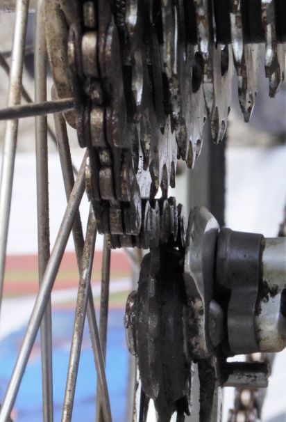
Improved spoke clearance with nut-less derailer cage.
Discussion of fastener selection and modification to follow in Post #51
8 sprockets on 7-speed cassette
First, because this is going to be a keeper, not just proof of concept, I sprang for some new parts instead of rummaging through my junk bins:
NOS Hyperglide 7-speed cassette, 13-23 T
Barely used Maillard freewheel sprocket 26 teeth.
NOS Uniglide 23 tooth cassette sprocket (just because I stumbled on it while searching eBay and realized it would allow me to avoid drilling holes in the 23-tooth sprocket of my new cassette.)
Fasteners were the challenge and will get a full treatment in a subsequent separate post (#51). There might be easier ways of doing this but nothing else that was available to me in stainless steel and gave me the appearance and clearance I was aiming for.
26T sprocket (cropped from seller's listing)
Uniglide 23T (cropped from seller's listing)
Countersunk sleeve nuts, as obtained. (cropped from seller's listing) See next post for explanation. Male halves are stainless steel machine screws. Spacers between sprockets will be Presta valve-stem nuts as before.
I prepared the fasteners first, (see post #51) before drilling holes, because I wasn't sure what I was going to end up with. The plan was to put male machine screws through small holes in the Uniglide sprocket and female sleeve nuts through larger holes in the freewheel sprocket. I'll explain the sizing later but what you see in the finished product are SAE 8-32 screws going into sleeve nuts that started out as blind-end M5 but were drilled out and tapped to 8-32.
First, as with the proof-of-concept version described earlier, I worked out where the holes could safely (or boldly?...) go without fouling the chain or leaving too little metal in the web of the Uniglide sprocket. The freewheel sprocket was thick and had lots of metal, so larger holes go in this piece. I was hoping that the lightening holes already drilled in the latter might serve for fastening but no such luck -- they're in the wrong place. I used a grinding bit in a cordless drill to scuff a divot into the surface hardening around the probable hole locations of both pieces, in order to be able to get a drill bit started. I scratched an index mark (with a file handle tip) at one hole location on both pieces to aid in alignment for later assembly. Because the holes were going to be drilled by eye, only one of six possible clock orientations would match up. I carefully aligned the two sprockets to get them as close to concentric as I could and, after verifying that a hole drilled through the upper would continue on in the right place through the lower, I clamped them to my backing board and to the workbench.
The scuffed Ultraglide sprocket accepted a centre punch with a solid whack. A good cobalt drill bit went right through it and started nicely into the freewheel sprocket below. I don't have a drill press so I used my old corded power drill, with the speed lock set slow enough to drill in steel without overheating. Lots of oil and heavy pressure applied vertically onto a low bench. Eye protection, leather gloves, proper shoes, and a shop apron. With six holes drilled into the Uniglide sprocket, I unclamped it and finished the larger holes through the freewheel sprocket, through which the female half of the sleeve nut will pass. The black oxide Dewalt bits from the set in the yellow box work very well as I didn't have a cobalt bit large enough. Again, slow speed, heavy pressure, lots of oil. Didn't see any smoke from any of the 12 holes and didn’t break any bits.
Next was to countersink the holes on the correct sides. Both sprockets were ever so slightly thinner than the countersunk portions of the fasteners that would seat into them. That meant that to countersink them completely, the far side of each hole would have to be larger than the shaft diameter of the screw or sleeve nut (as the case may be.) I didn't want to make the hole in the Uniglide sprocket any bigger than the screw, and I didn't want the shoulder of the sleeve nut poking through the freewheel sprocket where it might interfere with the seating of the spacers (which were already a snug fit over the sleeve nuts.) So I just countersunk (sank?) until there was a sharp edge on the far side of each hole, indicating that any further would start to enlarge the hole. That's why in the photos you can see that the fasteners aren't quite flush with the sprockets. (The oval heads are meant to bulge up above the surface, but there is more than just the oval that is proud if you look closely.) This was hard work. I've tried a variety of countersinks in steel and none are really satisfactory in a hand drill. Make sure you're countersinking the correct side of each sprocket!
Edit: The sleeve nuts have to be trimmed so that they don't protrude above the valve-nut spacers that slip on over them. Because of the less than perfect countersinking, it's impossible to predict this length precisely beforehand. So I cut them to rough length first, then filed and ground them down until flush with the spacers. Careful, because the valve nuts are softer than then the sleeve nuts. The idea was to leave as much thread as possible for the machine screws. See post #51.
That done, it was simple to bolt the pieces together, [Edit: trim off the excess length of the machine screws], reassemble the cassette, and Voil�, 8 speeds on 7. I also swapped out the old rear derailer, which has a jockey pulley nut on the inside of the cage, for a newer one that doesn't, just to give a bit more clearance to the spokes and take advantage of newer technology. (Farewell, Suntour....but the shifters are still Suntour.)
Top side. Scuffed-off surface hardening is seen particularly at 10 o'clock screw
Bottom side. Machine screw ends trimmed flush with the sleeve nuts. Hand-made slots visible in drilled-through sleeve nut heads.
Note slight protrusion of sleeve nut heads above the countersunk surface to left. Ditto with oval heads to right.
.
Improved spoke clearance with nut-less derailer cage.
Discussion of fastener selection and modification to follow in Post #51
Last edited by conspiratemus1; 09-14-19 at 11:06 PM.
09-12-19, 09:29 PM
#49
Member
Thread Starter
Thank you! Your detailed writeup and photos makes duplication of this project easy. (for the two of us in the world that are interested in doing this)
In your first photo, the space between the 26t and 23t cogs looks 1mm narrower than the space between the other cogs - is that right? Obviously, it doesn't matter to your shifting.
I'm going to guess based on my experience with the hardened cog that yours are not hardened. I couldn't even scratch the surface hardening with a cobalt bit.
It makes me happy to see someone spell 'voila' correctly (with the accent even!). I'm reading too many internet comments with people spelling it "walla", etc.
Which derailleur got retired and which one is now in service? Which Suntour shifters? I retired a very pretty black Cyclone rear short cage when I moved to Colorado. I'm currently running a bland looking silver Cyclone MkII long cage. I suspect a long cage Cyclone Mk I isn't going to handle 34t with my short derailleur hanger. Curiously, I have Shimano 600 Arabesque shifters. I'm debating going with Superbe shifters. Both are pretty.
In your first photo, the space between the 26t and 23t cogs looks 1mm narrower than the space between the other cogs - is that right? Obviously, it doesn't matter to your shifting.
I'm going to guess based on my experience with the hardened cog that yours are not hardened. I couldn't even scratch the surface hardening with a cobalt bit.
That done, it was simple to bolt the pieces together, [Edit: trim off the excess length of the machine screws], reassemble the cassette, and Voil�, 8 speeds on 7. I also swapped out the old rear derailer that has a jockey pulley nut on the inside of the cage for a newer one that doesn't, just to give a bit more clearance to the spokes and take advantage of newer technology. (Farewell, Suntour....but the shifters are still Suntour.)
Which derailleur got retired and which one is now in service? Which Suntour shifters? I retired a very pretty black Cyclone rear short cage when I moved to Colorado. I'm currently running a bland looking silver Cyclone MkII long cage. I suspect a long cage Cyclone Mk I isn't going to handle 34t with my short derailleur hanger. Curiously, I have Shimano 600 Arabesque shifters. I'm debating going with Superbe shifters. Both are pretty.
09-12-19, 10:02 PM
#50
Used to be Conspiratemus
Join Date: Jan 2009
Location: Hamilton ON Canada
Posts: 1,512
Mentioned: 4 Post(s)
Tagged: 0 Thread(s)
Quoted: 297 Post(s)
Liked 245 Times
in
163 Posts
Thank you! Your detailed writeup and photos makes duplication of this project easy. (for the two of us in the world that are interested in doing this)
In your first photo, the space between the 26t and 23t cogs looks 1mm narrower than the space between the other cogs - is that right? Obviously, it doesn't matter to your shifting.
I'm going to guess based on my experience with the hardened cog that yours are not hardened. I couldn't even scratch the surface hardening with a cobalt bit....
The valve-nut spacers are 3 mm (I picked through mine to get six the same); the other spacers are 3.15 mm (standard Shimano 7-speed.)
Old derailer was Suntour α-5000, "new"one is a Shimano 105 that actually has been on that bike previously but had a seized upper pivot, now restored.
Likes For conspiratemus1:

