


Attach small sprocket to front bottom bracket square tapered axle?
 10-03-19, 10:31 AM
#1
Junior Member
Thread Starter

Attach small sprocket to front bottom bracket square tapered axle?
That's the specific question.
I have an ordinary BMX low-end racing bike "Redline Expert". The pedals have been removed. There will be no pedals on this bike. Now I need a smaller sprocket (fewer teeth) on the front bottom bracket than on the rear axle hub. I'm sure the back wheel hub is an ordinary freewheel hub. So I guess that limits the tooth count back there to 21 or so (unless I want to use a cassette, I don't). In other words... I need a negative gear ratio.
I have some ideas on how to attach a small sprocket on the front bottom bracket square tapered axle. Years ago, I was trying to do this same thing, and I found a metal piece that might be useful. Will include a picture, FWIW. And here I go again. But if anyone has their own ideas, maybe having done it before, I'm all ears. Happy to clarify if needed. Can post more pictures.
To summarize... BMX bike. Need fewer teeth sprocket in front and more teeth sprocket in back. How is that supposed to happen?
Thanks.
 10-03-19, 10:43 AM
#2
Senior Member
Join Date: Jan 2013
Location: Llano Estacado
Posts: 3,702
Bikes: old clunker
Mentioned: 13 Post(s)
Tagged: 0 Thread(s)
Quoted: 684 Post(s)
Likes: 0
Liked 105 Times
in
83 Posts
That's the specific question.
I have an ordinary BMX low-end racing bike "Redline Expert". The pedals have been removed. There will be no pedals on this bike. Now I need a smaller sprocket (fewer teeth) on the front bottom bracket than on the rear axle hub. I'm sure the back wheel hub is an ordinary freewheel hub. So I guess that limits the tooth count back there to 21 or so (unless I want to use a cassette, I don't). In other words... I need a negative gear ratio.
I have some ideas on how to attach a small sprocket on the front bottom bracket square tapered axle. Years ago, I was trying to do this same thing, and I found a metal piece that might be useful. Will include a picture, FWIW. And here I go again. But if anyone has their own ideas, maybe having done it before, I'm all ears. Happy to clarify if needed. Can post more pictures.
To summarize... BMX bike. Need fewer teeth sprocket in front and more teeth sprocket in back. How is that supposed to happen?
Thanks.
10-03-19, 10:44 AM
#3
Senior Member

Join Date: Sep 2010
Location: Roswell, GA
Posts: 8,319
Bikes: '93 Trek 750, '92 Schwinn Crisscross, '93 Mongoose Alta
Mentioned: 30 Post(s)
Tagged: 0 Thread(s)
Quoted: 1438 Post(s)
Liked 1,092 Times
in
723 Posts
You don't want a negative ratio, that would turn the rear wheel backwards, you want a reduction ratio, or less than 1:1. I also doubt that the metal piece pictured will take the stresses of pedaling. But then you say the bike will have no pedals, are you planning an electric drive or something?
10-03-19, 10:46 AM
#4
Senior Member
Join Date: May 2003
Location: Mountain Brook. AL
Posts: 4,002
Mentioned: 14 Post(s)
Tagged: 0 Thread(s)
Quoted: 303 Post(s)
Likes: 0
Liked 136 Times
in
104 Posts
Just guessing but IF the width of the square is intended to bottom out on the square taper part of the spindle, then I
am assuming the square cutout is no more than 0.5" wide, so your circle is ~1.5" in diameter. This would allow
at minimis a 14t cog. Depending on the torque expected, you might find such on a cassette especially a cassette
with a small cog of 11t and tight stepping. Such a cog would probably have a sufficiency of space to allow
both cog and your ring to be drilled and tapped for 5Mx0.8 screws, 4 of which should suffice. You would then
need some spacers inboard and outboard to keep the apparatus on the taper and not wobbly. A hammer to flatten
the prongs. For a comparison disk brake discs are held on by 4 or 5 5M screws and hold up to the torque fine.
Likes For sch:
10-03-19, 11:53 AM
#5
Junior Member
Thread Starter
Yes, the width of the anti-turn washer inner square is 0.532" and as I recall it does fit snugly on the end of the square tapered spindle. The outer diameter is 1.756".
Thanks to the replies.
Thanks to the replies.
Last edited by Badzilla; 10-03-19 at 01:05 PM.
10-03-19, 01:06 PM
#6
Senior Member
Join Date: May 2003
Location: Mountain Brook. AL
Posts: 4,002
Mentioned: 14 Post(s)
Tagged: 0 Thread(s)
Quoted: 303 Post(s)
Likes: 0
Liked 136 Times
in
104 Posts
I was also assuming peak to trough height on the teeth at 5/16 but really closer to 0.13", after I decided to go to the garage and look at some
soon to be recycled cogs from 10 spd cassettes: 15T cog OD trough to trough is 2", 14T same is 1.87" so if you use your rounds,
a 14T cog could be used. They have (on Shimano cassettes) a plethora of 3/16" holes already there so you would only have
to drill the round you have. So chain clearance is adequate. A carefully placed bolt circle inside the splined area could be used as well, but
getting 4 bolts in there might be tight. 13T cog? OD of trough to trough very close to your 1.756" round.
This would have to be mounted carefully probably inside the splines, so probably could be used by filing a half round inside
the spline circle for mounting bolts. So based on my Shimano cogs a 13T is the smallest feasible.
Further thoughts: using a chainsaw blade file you could make the half rounds inside the spline easily enough and by placing them
at the same place on 13 or 14 or 15T cog you could easily replace one with another. Should be possible to get 4 mounting bolts in
there.
Last edited by sch; 10-03-19 at 01:12 PM.
Likes For sch:
10-03-19, 09:39 PM
#7
Generally bewildered

Join Date: Aug 2015
Location: Eastern PA, USA
Posts: 3,037
Bikes: 2014 Trek Domane 6.9, 1999 LeMond Zurich, 1978 Schwinn Superior
Mentioned: 20 Post(s)
Tagged: 0 Thread(s)
Quoted: 1152 Post(s)
Liked 341 Times
in
251 Posts
Note that square taper spindles are just that: tapers. Anything that drives the wheel will have to be fastened onto the taapered spindle with a matching tapered hole. And tapered holes that are fit with close enough tolerance are NOT attainable with just a file. In the machine tool industry tapers are used a lot and to get an accurate taper you first machine the hole with a precision tapered reamer, and then you use a laborious process for experts called scraping. You use lamp black or a special dye or other very fine powder in mineral oil, apply to taper or hole, then mate the two and separate. You take a purpose-designed scraper (kind of like if a file had the tip ground and lapped to give you a very sharp edge) and you hand scrape the high points (which are highlighted by your dye). To do a round taper, with the proper tools, might take an hour by an expert and several days by a neophyte.
The circles you have their will last about two minutes if you are pedaling and about 30 seconds if you have a motor hooked up to the thing. They will fail by loosening, and then rapidly wearing and finally yielding to leave you with very rough by nicely rounded holes. If you want something that will work, find a suitable crank and cut off the crank arms and fasten a gear onto the truncated arms.
To do the square holes in your own raw stock you'd drill first and then use use a tool called a broach. First to get a square hole. Then set up to get the taper. Look broaching up.
This is not a trivial exercise where washers with rough square holes, and JB Weld will suffice.
You might think about finding a BB with a different spindle type that is more amenable to home-made mods like this.
Last edited by WizardOfBoz; 10-03-19 at 09:43 PM.
10-04-19, 05:26 AM
#8
Junior Member
Thread Starter
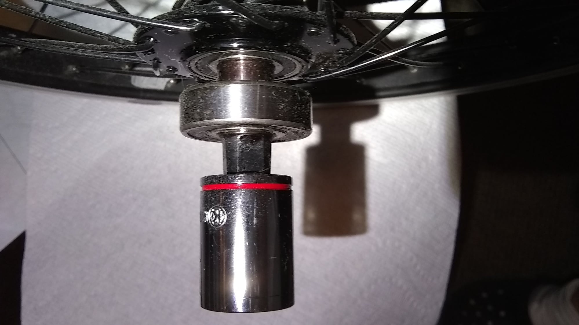
I have been using a 1/2 inch drive untapered socket pressed (by the spindle bolt) onto the end of a square tapered spindle, under the same force, for years.
10-04-19, 06:16 AM
#9

Senior member

Join Date: Oct 2004
Location: Oakville Ontario
Posts: 8,115
Mentioned: 25 Post(s)
Tagged: 0 Thread(s)
Quoted: 942 Post(s)
Liked 656 Times
in
370 Posts
I think the way I would approach the problem would be to start with a square taper crank, a cheap steel one would be best, cut off the crank arm, and cut or mill what's left to mount whatever drive mechanism you intend to use.
 10-04-19, 06:45 AM
#10
Senior Member
Join Date: Aug 2005
Location: Pittsburgh, PA
Posts: 33,656
Bikes: '96 Litespeed Catalyst, '05 Litespeed Firenze, '06 Litespeed Tuscany, '20 Surly Midnight Special, All are 3x10. It is hilly around here!
Mentioned: 39 Post(s)
Tagged: 0 Thread(s)
Quoted: 2026 Post(s)
Likes: 0
Liked 1,095 Times
in
741 Posts
10-04-19, 07:37 AM
#11
Generally bewildered
Join Date: Aug 2015
Location: Eastern PA, USA
Posts: 3,037
Bikes: 2014 Trek Domane 6.9, 1999 LeMond Zurich, 1978 Schwinn Superior
Mentioned: 20 Post(s)
Tagged: 0 Thread(s)
Quoted: 1152 Post(s)
Liked 341 Times
in
251 Posts
Ok, so you have a crank spindle where a wheel axle goes, and you have an outboard bearing AND a wheel bearing. You drive the spindle and it spins in both bearings. So what are you driving, exactly?
Anyway, a spindle will be made of strong, hardened steel. Chromoly probably, or maybe 8650. A socket is generally made from chrome vanadium, S2, or 8650. All strong steels that are hardened and tempered. The square socket is much wider than the washers you show. A press fit of a hardened socket onto a fairly well-tempered spindle might deform the spindle enough to make a reasonably conformal fit, and with the crank screw this could be why this has held together. A couple questions:
1) Is the socket used to drive the spindle under significant load? It looks like the socket drives a spindle that just spins in a wheel. If the torque is low this lowers service duty and makes the ad hoc designs you have implemented and proposed more likely to work.
2) Is the socket used to drive the spindle constantly, or just for starting purposes?
3) Is this setup used for cycling at all? Is this for a bike or some bizarre contraption?
If this isn't for a bike (and you're using the spindle as a machine tool or something, with no road shock and low service duty levels) you might get the washers to work. But I'd bet not:
1) The washers are likely made out of the cheapest mild steel available and are almost certainly not hardened.
2) The washers are thin. This increases stress level for a given service duty.
3) The washers are thin. This lowers the mechanical stability (your gear is likely to wobble).
All this makes deformation and rounding out more likely.
Given that your spindle has two bearings on the socket side, I'm curious as to what the heck you're making.
Last edited by WizardOfBoz; 10-04-19 at 07:40 AM.
10-04-19, 11:57 PM
#12
Senior Member
50.4mm bcd crank arm. Tourists and tandems wanting extra low gears have been mounting freewheel cogs onto them since forever. Requires a bit of machine shop work but no big deal and all pretty obvious. For those wanting triple and quad cranks there's a lot of work on the bolts, if running just the one cog it should be very simple. But what on earth is a bike with no pedals? Is this a motorcycle? How much power is doing what?
10-06-19, 01:05 PM
#13
Junior Member
Thread Starter
It's another way, direct drive, a cordless drill can power an electric bike. All that stuff might be in my posting history here. A DeWalt DCD991 cordless drill works well. The drill spindle accommodates a 0.5" x 20 thread per inch nut, or certain lug nuts with the same thread dimensions. That fits into the socket shown in the picture, either 19 mm or slightly larger for a lug nut.


