


Wahoo Kickr Circuit Board Repair
 02-16-24, 01:20 PM
#226


Randomhead
Join Date: Aug 2008
Location: Happy Valley, Pennsylvania
Posts: 24,399
Mentioned: 0 Post(s)
Tagged: 0 Thread(s)
Quoted: 4 Post(s)
Liked 3,699 Times
in
2,519 Posts
AFAIK, rogers2000 doesn't monitor this thread any more. It seems you are in Europe, so you might want to contact the company in the U.K. that fixes kickrs. No experience with them though.
https://www.theturbotrainerdoctor.com/contact
https://www.theturbotrainerdoctor.com/contact
 02-26-24, 08:38 AM
#227
Newbie
Join Date: Nov 2023
Posts: 8
Mentioned: 0 Post(s)
Tagged: 0 Thread(s)
Quoted: 3 Post(s)
Likes: 0
Liked 1 Time
in
1 Post
Hi @SixOnine, the one I managed to fix with aluminum tape was a 2014 version. Does yours power up and register in the app?
 02-26-24, 08:42 AM
#228
Newbie
Join Date: Nov 2023
Posts: 8
Mentioned: 0 Post(s)
Tagged: 0 Thread(s)
Quoted: 3 Post(s)
Likes: 0
Liked 1 Time
in
1 Post
02-26-24, 11:41 AM
#229
Newbie
Join Date: Feb 2024
Posts: 3
Mentioned: 0 Post(s)
Tagged: 0 Thread(s)
Quoted: 1 Post(s)
Likes: 0
Liked 0 Times
in
0 Posts
02-26-24, 02:11 PM
#230
Randomhead
Join Date: Aug 2008
Location: Happy Valley, Pennsylvania
Posts: 24,399
Mentioned: 0 Post(s)
Tagged: 0 Thread(s)
Quoted: 4 Post(s)
Liked 3,699 Times
in
2,519 Posts
I suppose it's possible the port on the microcontroller could be dragging it down.
Can you upload a picture of your controller board? You can't post it here, but if you upload it to an album in your gallery, I can rescue it for you.
unterhausen I'm not an electronics whiz, but how would I test the capacitors? I'm in NJ - can I send the board to someone if I can't manage to diagnose/fix myself?
Did you clean the sensor?
Last edited by unterhausen; 02-26-24 at 02:21 PM.
02-26-24, 06:25 PM
#232
Newbie
Join Date: Feb 2024
Posts: 1
Mentioned: 0 Post(s)
Tagged: 0 Thread(s)
Quoted: 0 Post(s)
Likes: 0
Liked 0 Times
in
0 Posts
So I thought I should just start posting ( not spamming) because I am in the early stages of trying to fix my v5. If the circuit t board is fried them would I be getting 0.0 for speed or -.- ?
02-27-24, 02:03 AM
#233
Randomhead
Join Date: Aug 2008
Location: Happy Valley, Pennsylvania
Posts: 24,399
Mentioned: 0 Post(s)
Tagged: 0 Thread(s)
Quoted: 4 Post(s)
Liked 3,699 Times
in
2,519 Posts
Are the LED's flashing? If not, you have bigger problems
02-27-24, 10:08 AM
#234
Newbie
Join Date: Nov 2023
Posts: 8
Mentioned: 0 Post(s)
Tagged: 0 Thread(s)
Quoted: 3 Post(s)
Likes: 0
Liked 1 Time
in
1 Post
unterhausen I'm not an electronics whiz, but how would I test the capacitors? I'm in NJ - can I send the board to someone if I can't manage to diagnose/fix myself?
pulled the board and it does look discolored (see latest pics in my gallery)
not sure how to test with the multimeter? Resistance mode? black to ground? red to either side of the cap?
Last edited by six0nine; 02-27-24 at 10:52 AM.
02-27-24, 12:22 PM
#235
Randomhead
Join Date: Aug 2008
Location: Happy Valley, Pennsylvania
Posts: 24,399
Mentioned: 0 Post(s)
Tagged: 0 Thread(s)
Quoted: 4 Post(s)
Liked 3,699 Times
in
2,519 Posts
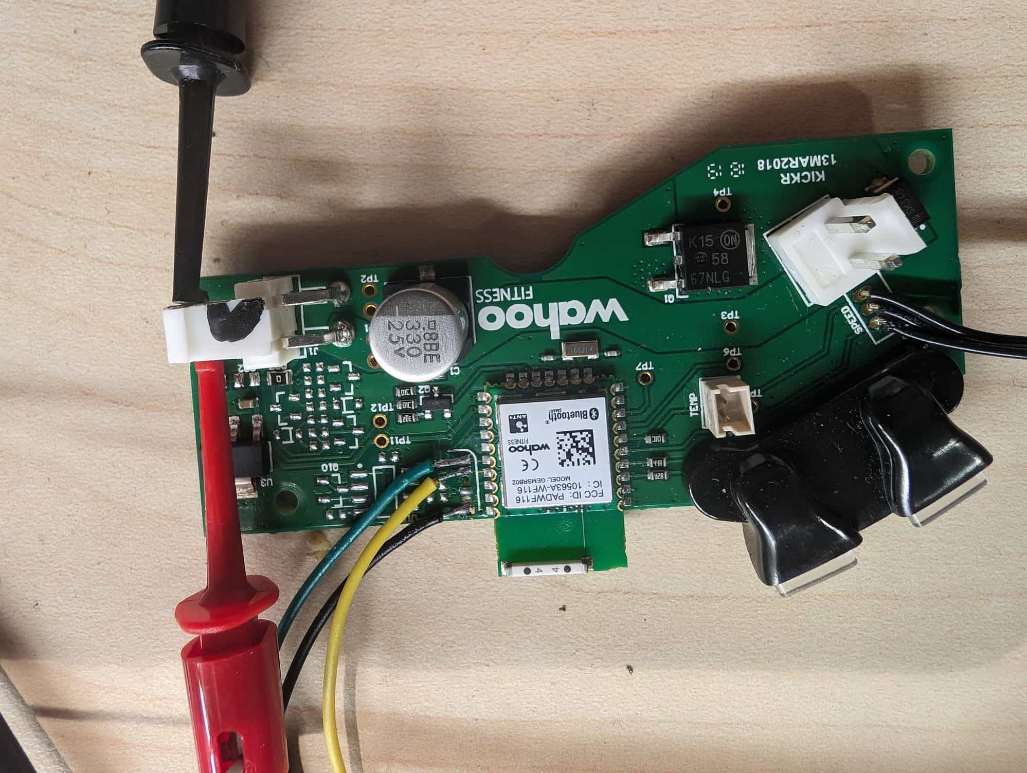
If you are talking about the discoloration in the middle right of the underside, that seems pretty normal. The device on top is the braking transistor.
I can't read the part number on the voltage regulator, I would check the voltages between the three pins. The big tab should be 12v, and I think the left one is 3.3 volts. You should be able to pick up ground from any of the vias on the big ground plane attached to the black wire from the voltage input.
I can't read the part number on the voltage regulator, I would check the voltages between the three pins. The big tab should be 12v, and I think the left one is 3.3 volts. You should be able to pick up ground from any of the vias on the big ground plane attached to the black wire from the voltage input.
02-28-24, 11:13 AM
#236
Newbie
Join Date: Feb 2024
Posts: 4
Mentioned: 0 Post(s)
Tagged: 0 Thread(s)
Quoted: 0 Post(s)
Likes: 0
Liked 0 Times
in
0 Posts
How to read
Hi I was wonder how to read the NRF52832 with jlink?
never used this before so don�t know how to read the chip to write onto the new one, I will need the commands used as I got a connection
never used this before so don�t know how to read the chip to write onto the new one, I will need the commands used as I got a connection
02-28-24, 11:19 AM
#237
Randomhead
Join Date: Aug 2008
Location: Happy Valley, Pennsylvania
Posts: 24,399
Mentioned: 0 Post(s)
Tagged: 0 Thread(s)
Quoted: 4 Post(s)
Liked 3,699 Times
in
2,519 Posts
It's not the most organized, but I listed the commands in this post: https://www.bikeforums.net/23126434-post215.html
I probably should color code user inputs, but if you follow closely it's not too hard to see which things you need to type in.
I probably should color code user inputs, but if you follow closely it's not too hard to see which things you need to type in.
02-28-24, 01:20 PM
#238
Newbie
Join Date: Feb 2024
Posts: 4
Mentioned: 0 Post(s)
Tagged: 0 Thread(s)
Quoted: 0 Post(s)
Likes: 0
Liked 0 Times
in
0 Posts
Thanks I get error could not read memory so don�t know what the issue is
Last edited by johnjones; 02-28-24 at 01:51 PM.
02-28-24, 01:52 PM
#239
Newbie
Join Date: Feb 2024
Posts: 4
Mentioned: 0 Post(s)
Tagged: 0 Thread(s)
Quoted: 0 Post(s)
Likes: 0
Liked 0 Times
in
0 Posts
Thanks I managed to read them 2 files, so now I just program them 2 files on the new NRF52832 ?
02-28-24, 02:09 PM
#240
Randomhead
Join Date: Aug 2008
Location: Happy Valley, Pennsylvania
Posts: 24,399
Mentioned: 0 Post(s)
Tagged: 0 Thread(s)
Quoted: 4 Post(s)
Liked 3,699 Times
in
2,519 Posts
right. Unintuitively called, "loadfile"
If you saved your binary in binary_UICR_1.bin, then the command is:
loadfile binary_UICR_1.bin 0x10001000
Firmware proper:
Similarly, if you saved the main firmware in binary_firmware_1.bin, the command is:
loadfile binary_firmware_1.bin 0x0
If you saved your binary in binary_UICR_1.bin, then the command is:
loadfile binary_UICR_1.bin 0x10001000
Firmware proper:
Similarly, if you saved the main firmware in binary_firmware_1.bin, the command is:
loadfile binary_firmware_1.bin 0x0
02-28-24, 11:11 PM
#241
Newbie
Join Date: Feb 2024
Posts: 4
Mentioned: 0 Post(s)
Tagged: 0 Thread(s)
Quoted: 0 Post(s)
Likes: 0
Liked 0 Times
in
0 Posts
right. Unintuitively called, "loadfile"
If you saved your binary in binary_UICR_1.bin, then the command is:
loadfile binary_UICR_1.bin 0x10001000
Firmware proper:
Similarly, if you saved the main firmware in binary_firmware_1.bin, the command is:
loadfile binary_firmware_1.bin 0x0
If you saved your binary in binary_UICR_1.bin, then the command is:
loadfile binary_UICR_1.bin 0x10001000
Firmware proper:
Similarly, if you saved the main firmware in binary_firmware_1.bin, the command is:
loadfile binary_firmware_1.bin 0x0
03-29-24, 03:50 PM
#242
Newbie
Join Date: Feb 2024
Posts: 3
Mentioned: 0 Post(s)
Tagged: 0 Thread(s)
Quoted: 1 Post(s)
Likes: 0
Liked 0 Times
in
0 Posts
I was wondering if someone could help me, I recently got the GEM2 DevKit from North Pole and it connects to the PC via USB. I don't know what program I should use to copy the binary though as it isn't showing up through Jlink at all. Thank in advance.
04-01-24, 02:25 AM
#243
Newbie
Join Date: Feb 2024
Posts: 6
Mentioned: 0 Post(s)
Tagged: 0 Thread(s)
Quoted: 0 Post(s)
Likes: 0
Liked 0 Times
in
0 Posts
Hey folks, I need some help.
It all started that my Wahoo didn't give any readings (0W always). So I started to disassemble.
When I inject a 1.2v signal with a function generator, the app shows some power and it seems to be working fine.
I've already replaced the photo coupler and the IR LED of the coupler is working (checked with camera) and the voltage is 1.2V on the LED.
However, when using a mirror or white plastic, there are no readings in the app.
I'm lost and need some hints.
04-01-24, 07:35 AM
#244
Randomhead
Join Date: Aug 2008
Location: Happy Valley, Pennsylvania
Posts: 24,399
Mentioned: 0 Post(s)
Tagged: 0 Thread(s)
Quoted: 4 Post(s)
Liked 3,699 Times
in
2,519 Posts
It needs a square wave to generate power, so the mirror isn't going to do anything. Are you saying the voltage varies between 3.3v and 1.2v? I think the logic low should be below .7v or something like that. Silver tape over the white parts of the encoder wheel should get you there. It occurs to me that if it registers power with a signal generator, it's unlikely to be anything else. You have an issue with the sensor somehow. I would try aluminum duct tape on the encoder wheel. I'm not sure if any of the transient suppressor diodes can go bad and cause a problem, but if you measure the voltage at the module, that should tell you if that's the problem. Out of curiosity, where are you injecting the signal?
I have seen online that wahoo tells people that the temperature sensor can go bad. I have no idea how to test that yet, but as cost conscious as the design is, it probably is an RTD.
I have seen online that wahoo tells people that the temperature sensor can go bad. I have no idea how to test that yet, but as cost conscious as the design is, it probably is an RTD.
Last edited by unterhausen; 04-01-24 at 12:14 PM.
04-02-24, 02:03 AM
#245
Newbie
Join Date: Feb 2024
Posts: 6
Mentioned: 0 Post(s)
Tagged: 0 Thread(s)
Quoted: 0 Post(s)
Likes: 0
Liked 0 Times
in
0 Posts
Thanks for your reply! I was surprised that I do not see a change in signal on the coupler output whatever I do. So, yesterday I had another idea.
I de-soldered the wire going from the sensor board to the "mainboard" / �C and suddenly there are changes on the output pin of the opto coupler.
Whenever I re-connect the wire to the mainboard, the signal is pulled low.
I would love to share some pictures, but sadly as there is this 10 posts limitation, I cannot even use external http links
My question now: Is this signal going directly to the �C or are there any components in-between?
If not, the �C seems to have an issue.
If yes, I need to debug the mainboard a bit more.
Thanks for your help and this wonderful thread.
04-02-24, 04:27 PM
#246
Randomhead
Join Date: Aug 2008
Location: Happy Valley, Pennsylvania
Posts: 24,399
Mentioned: 0 Post(s)
Tagged: 0 Thread(s)
Quoted: 4 Post(s)
Liked 3,699 Times
in
2,519 Posts
What you can do is upload your pictures to an album in your gallery. Don't forget to hit the "upload" button on the upper right of the dialog box or they won't actually upload. Once you do that, one of us can rescue the pictures.
The circuit depends on the version of your kickr. They added some zeners on later versions to protect the microprocessor. They aren't in series with the sensor signal, they just go to power and ground. I'm pretty sure it goes direct to the chip otherwise. One of those zeners could be shorted, wouldn't surprise me. There are 3 of them right by the connector to the sensor board. If you used a signal generator to make it show power, then I doubt the microprocessor is bad. Your signal generator just overpowered whatever pulls down the signal. I have a schematic of the sensor board, but I wanted to actually put it in a schematic program instead of my awful sketch. Maybe I should upload a picture of the sketch.
The circuit depends on the version of your kickr. They added some zeners on later versions to protect the microprocessor. They aren't in series with the sensor signal, they just go to power and ground. I'm pretty sure it goes direct to the chip otherwise. One of those zeners could be shorted, wouldn't surprise me. There are 3 of them right by the connector to the sensor board. If you used a signal generator to make it show power, then I doubt the microprocessor is bad. Your signal generator just overpowered whatever pulls down the signal. I have a schematic of the sensor board, but I wanted to actually put it in a schematic program instead of my awful sketch. Maybe I should upload a picture of the sketch.
04-03-24, 12:36 AM
#247
Newbie
Join Date: Feb 2024
Posts: 6
Mentioned: 0 Post(s)
Tagged: 0 Thread(s)
Quoted: 0 Post(s)
Likes: 0
Liked 0 Times
in
0 Posts
Hello unterhausen , thanks again for your great support!
I've uploaded the pics to my gallery. Can you see it?
The board I have doesn't seem to have zeners. The resistance of the �C pin for the couple is definitely different from the once of the LEDs. Maybe an internal resistor in the �C (pull-down) becomes mad.
Or do you see any other option?
I've already read out the SW and have some spare controller boards from Aliexpress, but before removing the original �C board, I try to understand if there could be other failures.
04-03-24, 07:43 AM
#248
Randomhead
Join Date: Aug 2008
Location: Happy Valley, Pennsylvania
Posts: 24,399
Mentioned: 0 Post(s)
Tagged: 0 Thread(s)
Quoted: 4 Post(s)
Liked 3,699 Times
in
2,519 Posts
Thanks for posting pictures. You have one of the earlier boards with no protection. Later ones also have a connector for the sensor board. I haven't de-lidded one of the modules, but I think it's just a direct connection to the microprocessor. It probably does have pull up resistors built into the ports, that's pretty common with microcontrollers. I wish the manual was more like traditional chip company data sheets, I find it difficult to locate anything in it. I didn't post the other picture with no light on the sensor. I guess it's only showing 2.3v because there is some ambient light.
The later boards also have a more elaborate braking circuit. Have you checked to make sure that power transistor (Q1) isn't shorted?
The later boards also have a more elaborate braking circuit. Have you checked to make sure that power transistor (Q1) isn't shorted?
Last edited by unterhausen; 04-03-24 at 07:48 AM.
04-03-24, 01:42 PM
#249
Newbie
Join Date: Feb 2024
Posts: 6
Mentioned: 0 Post(s)
Tagged: 0 Thread(s)
Quoted: 0 Post(s)
Likes: 0
Liked 0 Times
in
0 Posts
unterhausen , thanks again for your continued support!
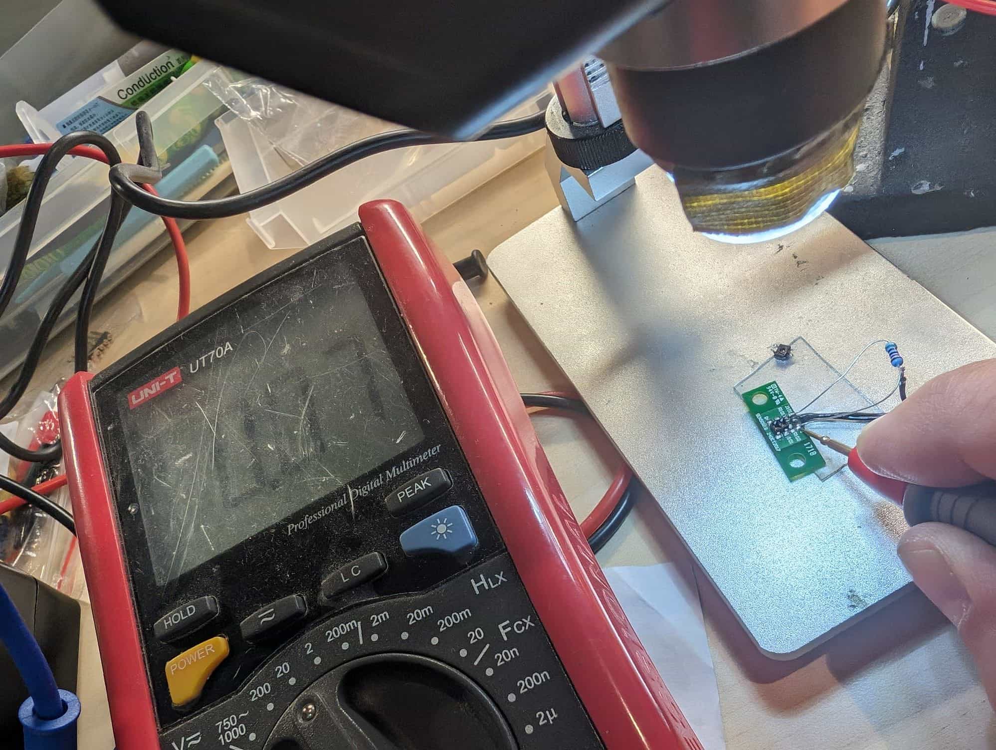
Here I need your help. I don't know how it should behave. Actually I'm more a SW guy, than a HW expert...
The measurements are again uploaded in my gallery.
What kind of power transistor (brand = ONSEMI?, model???) is it? I tried searching for k1558, but basically no results.
The later boards also have a more elaborate braking circuit. Have you checked to make sure that power transistor (Q1) isn't shorted?
The measurements are again uploaded in my gallery.
What kind of power transistor (brand = ONSEMI?, model???) is it? I tried searching for k1558, but basically no results.
Last edited by berton; 04-04-24 at 02:16 AM.
04-05-24, 09:36 AM
#250
Randomhead
Join Date: Aug 2008
Location: Happy Valley, Pennsylvania
Posts: 24,399
Mentioned: 0 Post(s)
Tagged: 0 Thread(s)
Quoted: 4 Post(s)
Liked 3,699 Times
in
2,519 Posts
It's a TK15