


Wheel lacing question
 10-29-20, 09:35 AM
#1
Member
Thread Starter
Wheel lacing question
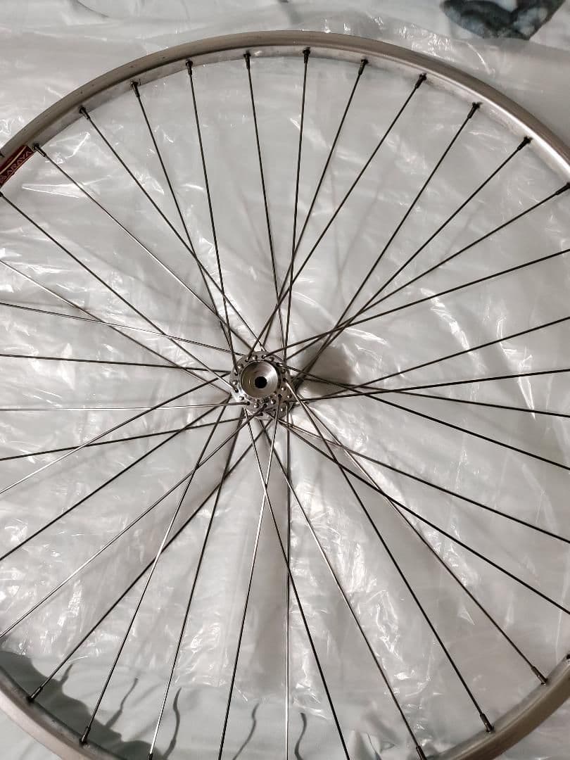
I bought a used vintage road bike. I'm cleaning it and putting it back together. I'm lacing the spokes on the wheels right now. I read Sheldon's lacing tutorial. I saw a couple videos online that are nice an clear. Should I lace the wheel how these resources tell me or would I be better off replicating the exact pattern that was on the wheel when I bought it? Thanks guys. Btw it's a 36 spoke 700c wheel.

Likes For alcjphil:
10-29-20, 09:59 AM
#3
Senior Member
Join Date: Dec 2010
Location: northern Deep South
Posts: 8,904
Bikes: Fuji Touring, Novara Randonee
Mentioned: 36 Post(s)
Tagged: 0 Thread(s)
Quoted: 2604 Post(s)
Liked 1,933 Times
in
1,213 Posts
Look carefully at the hub before you do anything different. There may be some spoke tracks bedded into the hub. If so, keep the same spoke pattern so you don't end up with spokes crossing the ridges on the hub and creating stress risers.
And as @alcjphil asked, what's different?
And as @alcjphil asked, what's different?
Likes For pdlamb:
10-29-20, 10:09 AM
#4
Member
Thread Starter
The original is pictured below. The original is the heads(don't know proper terminology, where the spoke attaches to the hub) are opposite. The heads are facing down and in turn instead of crossing two under one it looks like original goes under two and over one. But yeah pdlamb that makes sense. I just originally thought I could do better when that's not the case.

10-29-20, 10:32 AM
#5
Half way there

Join Date: Sep 2015
Location: North Carolina
Posts: 2,957
Bikes: Many, and the list changes frequently
Mentioned: 5 Post(s)
Tagged: 0 Thread(s)
Quoted: 986 Post(s)
Liked 880 Times
in
527 Posts
Good luck.
Also, that's a really clean wheel for being vintage. What bike are you restoring?
Likes For Moe Zhoost:
Likes For davidad:
10-29-20, 11:25 AM
#7
Member
Thread Starter
Yea sorry, I didn't do a very good job of illustrating it. The more I look at the hub the more I realize it's not only the direction the heads of the spokes are facing but a entirely different lacing pattern altogether. I tried whipping out Microsoft paint but gave up not wanting to force you nice people down an unnecessary rabbit hole . So instead I'll just concede that duplicating the original pattern and spoke orientation is the best idea.
Thanks for asking Moe Zhoost, It's a Nishiki Medalist. It's in great shape. I've spent time cleaning, degreasing and lubing as I go. It's a great mix of fun and challenging. I almost forgot I'd have something to ride when I'm all done.
Thanks for asking Moe Zhoost, It's a Nishiki Medalist. It's in great shape. I've spent time cleaning, degreasing and lubing as I go. It's a great mix of fun and challenging. I almost forgot I'd have something to ride when I'm all done.
10-29-20, 03:09 PM
#8
Really Old Senior Member

It's not inconceivable on a 36 spoke wheel, that it's laced 4X.
You are counting the 1st cross right at the hub flange aren't you?
You are counting the 1st cross right at the hub flange aren't you?
Likes For Bill Kapaun:
10-29-20, 05:13 PM
#9
Member
Thread Starter
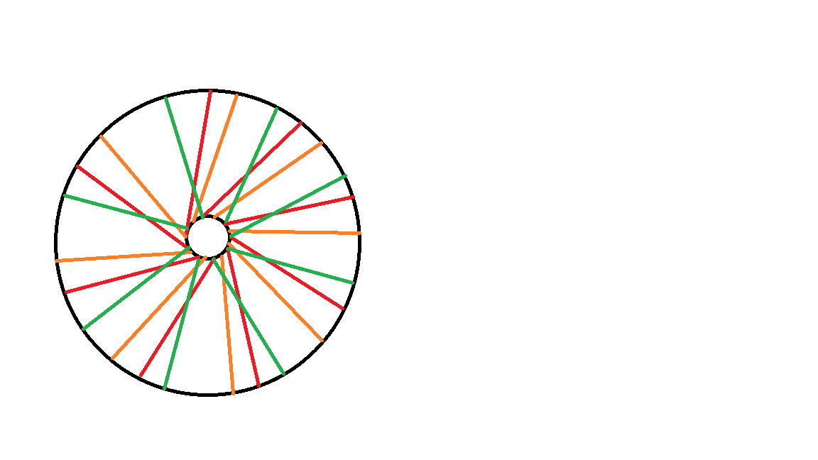
I never said anything crossed 4 times. I figures it out though. On my wheel spoke direction was opposite. So in the picture where red is going one way it's opposite on my wheel. And instead of the head of the spoke facing one way in my Sheldon tutorial, they're facing the other way. Since it was my first time making a wheel I wanted one "best" way. That way just happen to confuse me but it all lines up with my new understanding.
10-29-20, 06:19 PM
#10
Really Old Senior Member
IF the spoke holes on the rim are offset or angled "differently" from each other, you have to lace for the offset.
SOME rims are offset the "less conventional" way.
I didn't say "I never said anything crossed 4 times".
It was a question.
Your pic doesn't show the entire wheel and your drawing shows 2X.
Did you read this part of Sheldon?
"Rims are drilled either "right handed" or "left handed". This has to do with the relationship between the valve hole and the spoke holes. The spoke holes do not run down the middle of the rim, but are offset alternately from side to side. The holes on the left side of the rim are for spokes that run to the left flange of the hub. With some rims, the spoke hole just forward of the valve hole is offset to the left, with others it is offset to the right (as illustrated). Which type is "right handed" and which "left handed"? I have never met anyone who was willing to even make a guess!"
Last edited by Bill Kapaun; 10-29-20 at 06:25 PM.
10-29-20, 08:13 PM
#11
Senior Member
Join Date: Oct 2012
Location: Middle East, Melbourne, Victoria, Australia
Posts: 63
Mentioned: 0 Post(s)
Tagged: 0 Thread(s)
Quoted: 7 Post(s)
Likes: 0
Liked 8 Times
in
4 Posts
It is always confusing to try and describe wheel lacing in words, but yet I'll try.
I think the 'opposite' being referred to here is the difference between typical machine-built wheels and hand-built wheels.
In the photo the spokes that are pointing clockwise leave from the near side of the flange in both cases. That is they are 'heads in' on the near flange, and 'heads out' on the lower flange. Sheldon's method would have them all either heads in or heads out on both flanges. There is a whole other debate about whether it matters at all, and if it does which is the best.
As previously mentioned when hubs have been used for a while the spokes leave a mark on the hub flange. If you build the wheel with old hubs and you don't follow the existing marks you could create a stress riser which might result in a failure of the flange. If you are building using new hubs then I prefer Sheldon's method because I think it looks better.
Cheers,
Cameron
Likes For ironhanglider:
10-29-20, 08:46 PM
#12
Senior Member
I've seen wheels built this way before. It may make sense for a rear disk brake hub. Opinion varies on disk lacing patterns though.
For the OP, if the non-drive side flange has just light marks from the prior lacing, changing the different direction will be fine. The non-drive side spokes are not heavily tensioned anyway. Installing/weaving the spokes is easier if you follow the method that Sheldon uses. Doing all of the head-out spokes first causes less weaving on the 3rd & 4th set. And Sheldon's site has good direction, with diagrams.
For the OP, if the non-drive side flange has just light marks from the prior lacing, changing the different direction will be fine. The non-drive side spokes are not heavily tensioned anyway. Installing/weaving the spokes is easier if you follow the method that Sheldon uses. Doing all of the head-out spokes first causes less weaving on the 3rd & 4th set. And Sheldon's site has good direction, with diagrams.
Likes For KCT1986:
10-29-20, 09:11 PM
#13
Senior Member
Join Date: Dec 2019
Location: South Shore of Long Island
Posts: 2,799
Bikes: 2010 Carrera Volans, 2015 C-Dale Trail 2sl, 2017 Raleigh Rush Hour, 2017 Blue Proseccio, 1992 Giant Perigee, 80s Gitane Rallye Tandem
Mentioned: 12 Post(s)
Tagged: 0 Thread(s)
Quoted: 1088 Post(s)
Liked 1,024 Times
in
723 Posts
Did you read this part of Sheldon?
"Rims are drilled either "right handed" or "left handed". This has to do with the relationship between the valve hole and the spoke holes. The spoke holes do not run down the middle of the rim, but are offset alternately from side to side. The holes on the left side of the rim are for spokes that run to the left flange of the hub. With some rims, the spoke hole just forward of the valve hole is offset to the left, with others it is offset to the right (as illustrated). Which type is "right handed" and which "left handed"? I have never met anyone who was willing to even make a guess!"
"Rims are drilled either "right handed" or "left handed". This has to do with the relationship between the valve hole and the spoke holes. The spoke holes do not run down the middle of the rim, but are offset alternately from side to side. The holes on the left side of the rim are for spokes that run to the left flange of the hub. With some rims, the spoke hole just forward of the valve hole is offset to the left, with others it is offset to the right (as illustrated). Which type is "right handed" and which "left handed"? I have never met anyone who was willing to even make a guess!"
Likes For Russ Roth:
10-29-20, 09:34 PM
#14
Really Old Senior Member
I ran into this building a nos set of rims from the early 80s for someone. Usually with the rim laying flat and the driveside of the hub facing up I start lacing to the left of the valve stem, with those rims it was to the right of the valve stem that was the starting point. Also required changing which holes on the left flange had the trailing and pulling spokes. Yup, I screwed it up on the first try.
I'd get the 1st set right, but kept screwing up the indexing for the 2nd set.
About the 3rd wheel, the "light bulb" went off re: key spoke & indexing.
It seems so simple in hindsight, once you know what "the mission" is.
Likes For Bill Kapaun:
10-30-20, 02:21 PM
#16
Really Old Senior Member
On a "normal" offset, i start like Sheldon with the KEY spoke in the nipple hole next to the valve hole.
My 1st spoke of the 2nd set will go in the next nipple hole and go through the corresponding opposite flange hole as in the pic to the left. ( I work CCW)
IF the oddball offset-
Key spoke goes in the 2nd nipple hole from the valve.
My 1st spoke of the 2nd set will go in the nipple hole NEXT to the valve hole and go through the corresponding opposite flange hole as in the pic to the RIGHT.
10-31-20, 08:30 PM
#17
Used to be Conspiratemus
Join Date: Jan 2009
Location: Hamilton ON Canada
Posts: 1,512
Mentioned: 4 Post(s)
Tagged: 0 Thread(s)
Quoted: 297 Post(s)
Liked 245 Times
in
163 Posts
Funny I just encountered a similar oddity today, too. Since I think the OP's question has been answered, I'm going to add this:
Got an old C-Record front hub on eBay and, given there were spoke marks, I sought to duplicate the pattern from the fossil record, as it were.
OK, on a new hub, I always lace exactly as per Jobst Brandt's book, which I think is the same as Sheldon's: inbound spokes both sides first, first spoke to the left of the valve hole, then the first set of outbound spokes, then twist the hub to open up the pattern around the valve hole (which on a rear hub has to be also in the driving direction), lace those outbounds, then finish with the second set of outbound spokes. (If this isn't the same as Sheldon, don't tell me. I don't want to get confused. on my next wheel.) Never fails. I fail sometimes, if I lose count of skipped-over holes in the first set of spokes.
I've never seen a rim where the first hole to the left of the valve hole was offset downward as this would set the first spoke wrong by Jobst's metthod -- you'd be running it, and all others, from the "top" of the hub to the "bottom" side of the rim. Even if you flipped the rim over, the holes would still be oriented the same. You'd have to build the wheel "backward." But as Bill Kapaun says, presumably starting with the second nipple hole would fix that. But would the valve channel still open properly with rotation?
Usually on a used hub, it's easy to "set" the first spoke in such a way that the old pattern will be preserved, the valve will be clear, and you can see the logo or centre of the grease-port clip through the valve hole....unless the original builder was some amateur like me and made a mistake. But this hub was weird. The only way to meet those three requirements, or even the first two, was to have an out-bound spoke going into the first hole to the left of the valve hole. But outbound spokes would only be the third, or fourth set of spokes to go in. The placement of the first inbound spoke was a conundrum.. No matter where I put it, it was either going to close up the channel for the valve, or it was going to go to the wrong side of the rim, or the old spoke pattern would be violated, or the lacing would not be symmetrical (and then the spoke lengths would be all wrong. I wrestled with this most of the afternoon, but eventually I got it. I used a couple of temporary outbound spokes to set the pattern that the inbound spokes would have to fit, and finally it started to come together, but I had to lace one side first and then the other, which is more awkward. An outbound spoke from the top of the hub (when the wheel is lying on its side) goes to the first hole to the left of (and above) the valve hole. Other than that the wheel looks fine, tensioned up normally with correct spoke length all around..
I'm wondering if the hub was originally laced into one of these mythical "opposite" rims, where the first hole to the left of the valve hole is drilled below the hole. Would that explain why the hub had to be laced backward in order to re-create the spoke pattern in my rim with the "normal" offset-up drilling? If I had laced it normally, then the leading spokes would now be trailing and would be making new grooves in the hub shell about 120 degrees away from the old ones.
Fortunately this was a front hub.
(Not sure that a photo will add anything. When you track the first spoke to the left of the valve hole back to the hub, you see the elbow of the spoke at the flange instead of the head. Other that that, it just looks like a 3X 32-spoke wheel.)
Got an old C-Record front hub on eBay and, given there were spoke marks, I sought to duplicate the pattern from the fossil record, as it were.
OK, on a new hub, I always lace exactly as per Jobst Brandt's book, which I think is the same as Sheldon's: inbound spokes both sides first, first spoke to the left of the valve hole, then the first set of outbound spokes, then twist the hub to open up the pattern around the valve hole (which on a rear hub has to be also in the driving direction), lace those outbounds, then finish with the second set of outbound spokes. (If this isn't the same as Sheldon, don't tell me. I don't want to get confused.
on my next wheel.) Never fails. I fail sometimes, if I lose count of skipped-over holes in the first set of spokes.I've never seen a rim where the first hole to the left of the valve hole was offset downward as this would set the first spoke wrong by Jobst's metthod -- you'd be running it, and all others, from the "top" of the hub to the "bottom" side of the rim. Even if you flipped the rim over, the holes would still be oriented the same. You'd have to build the wheel "backward." But as Bill Kapaun says, presumably starting with the second nipple hole would fix that. But would the valve channel still open properly with rotation?
Usually on a used hub, it's easy to "set" the first spoke in such a way that the old pattern will be preserved, the valve will be clear, and you can see the logo or centre of the grease-port clip through the valve hole....unless the original builder was some amateur like me and made a mistake. But this hub was weird. The only way to meet those three requirements, or even the first two, was to have an out-bound spoke going into the first hole to the left of the valve hole. But outbound spokes would only be the third, or fourth set of spokes to go in. The placement of the first inbound spoke was a conundrum.. No matter where I put it, it was either going to close up the channel for the valve, or it was going to go to the wrong side of the rim, or the old spoke pattern would be violated, or the lacing would not be symmetrical (and then the spoke lengths would be all wrong. I wrestled with this most of the afternoon, but eventually I got it. I used a couple of temporary outbound spokes to set the pattern that the inbound spokes would have to fit, and finally it started to come together, but I had to lace one side first and then the other, which is more awkward. An outbound spoke from the top of the hub (when the wheel is lying on its side) goes to the first hole to the left of (and above) the valve hole. Other than that the wheel looks fine, tensioned up normally with correct spoke length all around..
I'm wondering if the hub was originally laced into one of these mythical "opposite" rims, where the first hole to the left of the valve hole is drilled below the hole. Would that explain why the hub had to be laced backward in order to re-create the spoke pattern in my rim with the "normal" offset-up drilling? If I had laced it normally, then the leading spokes would now be trailing and would be making new grooves in the hub shell about 120 degrees away from the old ones.
Fortunately this was a front hub.
(Not sure that a photo will add anything. When you track the first spoke to the left of the valve hole back to the hub, you see the elbow of the spoke at the flange instead of the head. Other that that, it just looks like a 3X 32-spoke wheel.)
