


Alignment thoughts
 11-22-18, 10:27 PM
#1

Senior Member
Thread Starter
Join Date: Feb 2012
Location: Rochester, NY
Posts: 18,099
Bikes: Stewart S&S coupled sport tourer, Stewart Sunday light, Stewart Commuting, Stewart Touring, Co Motion Tandem, Stewart 3-Spd, Stewart Track, Fuji Finest, Mongoose Tomac ATB, GT Bravado ATB, JCP Folder, Stewart 650B ATB
Mentioned: 0 Post(s)
Tagged: 0 Thread(s)
Quoted: 4211 Post(s)
Liked 3,881 Times
in
2,316 Posts
Alignment thoughts
I started this long winded post as a reply to Mike's recent thread. But as I sunk my teeth into this I decided it was more of a new topic and less a "Mike, what do you think of this" type reply. I've taken a lot of time and effort to consider alignment and read a lot from others far more experienced then I. So I've come to the belief that there's more then one "alignment" aspect when making frames that need to be considered.
By that I mean that there's three, IMO, aspects of alignment. Biomechanical, tracking/steering and design matching.
Biomechanical is about the rider sitting on center with the wheels, bars and cranks and whether the pedals are traveling in paths that are parallel planes to the frame's plane. Or more to the usual point- is the BB shell square with the frame's center plane. Measuring the frame's heights off the flat surface when the well faced shell is on a good post is the most common way to check this.
Tracking/steering is about the front and rear wheels sharing the same plane (when going straight ahead). Are the main triangle and the rear end centered to each other? Is the rear wheel in line (coplanier) top the main triangle? Are the head tube and the seat tube in the same plane (not twisted). And is the fork straight, the steerer lays on the same plane as the front wheel's?
Design alignment is whether the dimensions and angles intended are what the resulting frame actually has.
Each can exist independent of the others. A frame can track straight but have a twister BB shell. A BB shell can be square with the main triangle but the rear triangle can be off. The fork can be splayed but used in a straight frame. And both the first two aspects can be good but the resulting frame can have seat stays too short so that the BB drop and the head angle are off.
Note that it is the design alignment that a jig controls. Not the others. Sure the first two are likely to be less off when a jig is used but the jig really doesn't insure a biomechanical or tracking alignment completely. It is these that a flat surface and knowing how to use it does work for (and that flat surface won't self control the design alignment).
Using the face of a shell as the reference for either biomechanical or tracking alignments is a common method. What isn't usually mentioned in those discussions is that one can reface a shell a second (third...) time and result in a slightly different "squareness" of that face. Some tools are worse in this then others. Then there's the securing the frame to the BB post on the flat surface. These days it's relatively cheap to get dial indicators that show thousandths of an inch. record a measurement at a point along the seat tube (as example) remove the frame and resecure it then measure again. The read out is usually a tad different. Of course at some point things are "good enough", but when you can see thousandths... Then there's the issue of the tubes not really being round (made that way or brazing distortions). So if you flip the frame over you get a few discrepancies adding up. That second shell face will hold the frame a bit differently because it's a second tightening down and a different "square" WRT the tubes. The other sides of the tubes might not be the same distance from the virtual centerlines. I've seen more then 20 thousandths of change at times (that's .5mm).
So at what point and how measured do we call the frame right? Some builders will use the same shell face for all aligning steps. Some will only face the shell once at some point during their build sequence. Some will use pointers on surface gages instead of dials and not bother with tiny numbers. But there's a way that I have read and adopted that addresses most of these issues.
One is to separate the biomechanical from the tracking. BB shell squareness is done on the whipping post as is common. But tracking alignment is checked by what some call the Keith Bontrager method. The head tube is held on a shaft by end cones supported with risers off the flat surface. This insures the head tube's parallelness WRT the flat surface. The seat tube has one support located about half way along it's length. This support is vertically adjustable (machinist jack stand) and set at the same center height off the surface as the head tube. Now one can indicate along the seat tube and get a reference to the head tube with out how the shell is positioned influencing the comparison. (Of course one has rotationally positioned both the seat and head tubes so any bows are in line with the length of the frame, best possible). (This way of holding the frame isn't really for corrections/bending it into alignment, the whipping is for that).
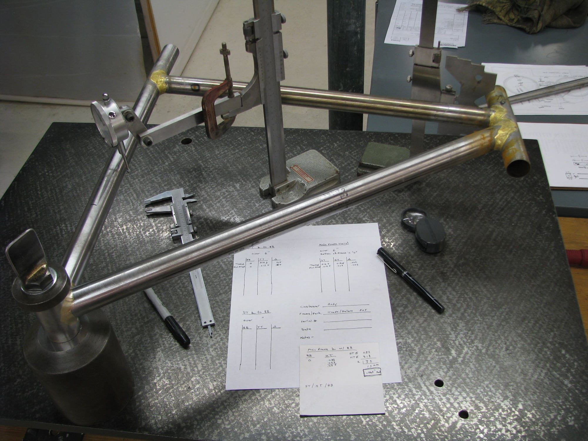
The common BB post set up.
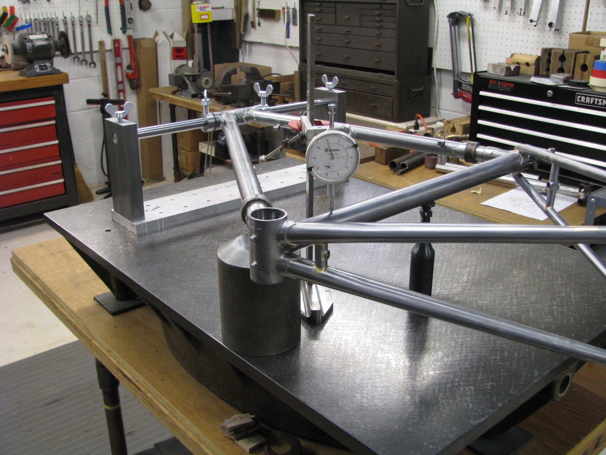
The Keith Bontrager method set up.
I will follow up with fork and rear end alignments soon. Commits welcome. Andy
By that I mean that there's three, IMO, aspects of alignment. Biomechanical, tracking/steering and design matching.
Biomechanical is about the rider sitting on center with the wheels, bars and cranks and whether the pedals are traveling in paths that are parallel planes to the frame's plane. Or more to the usual point- is the BB shell square with the frame's center plane. Measuring the frame's heights off the flat surface when the well faced shell is on a good post is the most common way to check this.
Tracking/steering is about the front and rear wheels sharing the same plane (when going straight ahead). Are the main triangle and the rear end centered to each other? Is the rear wheel in line (coplanier) top the main triangle? Are the head tube and the seat tube in the same plane (not twisted). And is the fork straight, the steerer lays on the same plane as the front wheel's?
Design alignment is whether the dimensions and angles intended are what the resulting frame actually has.
Each can exist independent of the others. A frame can track straight but have a twister BB shell. A BB shell can be square with the main triangle but the rear triangle can be off. The fork can be splayed but used in a straight frame. And both the first two aspects can be good but the resulting frame can have seat stays too short so that the BB drop and the head angle are off.
Note that it is the design alignment that a jig controls. Not the others. Sure the first two are likely to be less off when a jig is used but the jig really doesn't insure a biomechanical or tracking alignment completely. It is these that a flat surface and knowing how to use it does work for (and that flat surface won't self control the design alignment).
Using the face of a shell as the reference for either biomechanical or tracking alignments is a common method. What isn't usually mentioned in those discussions is that one can reface a shell a second (third...) time and result in a slightly different "squareness" of that face. Some tools are worse in this then others. Then there's the securing the frame to the BB post on the flat surface. These days it's relatively cheap to get dial indicators that show thousandths of an inch. record a measurement at a point along the seat tube (as example) remove the frame and resecure it then measure again. The read out is usually a tad different. Of course at some point things are "good enough", but when you can see thousandths... Then there's the issue of the tubes not really being round (made that way or brazing distortions). So if you flip the frame over you get a few discrepancies adding up. That second shell face will hold the frame a bit differently because it's a second tightening down and a different "square" WRT the tubes. The other sides of the tubes might not be the same distance from the virtual centerlines. I've seen more then 20 thousandths of change at times (that's .5mm).
So at what point and how measured do we call the frame right? Some builders will use the same shell face for all aligning steps. Some will only face the shell once at some point during their build sequence. Some will use pointers on surface gages instead of dials and not bother with tiny numbers. But there's a way that I have read and adopted that addresses most of these issues.
One is to separate the biomechanical from the tracking. BB shell squareness is done on the whipping post as is common. But tracking alignment is checked by what some call the Keith Bontrager method. The head tube is held on a shaft by end cones supported with risers off the flat surface. This insures the head tube's parallelness WRT the flat surface. The seat tube has one support located about half way along it's length. This support is vertically adjustable (machinist jack stand) and set at the same center height off the surface as the head tube. Now one can indicate along the seat tube and get a reference to the head tube with out how the shell is positioned influencing the comparison. (Of course one has rotationally positioned both the seat and head tubes so any bows are in line with the length of the frame, best possible). (This way of holding the frame isn't really for corrections/bending it into alignment, the whipping is for that).
The common BB post set up.
The Keith Bontrager method set up.
I will follow up with fork and rear end alignments soon. Commits welcome. Andy
__________________
AndrewRStewart
AndrewRStewart
 11-23-18, 02:55 AM
#2
Junior Member
Join Date: Nov 2015
Posts: 185
Mentioned: 0 Post(s)
Tagged: 0 Thread(s)
Quoted: 45 Post(s)
Likes: 0
Liked 44 Times
in
23 Posts
After you post the other day Andy I was trying to figure out how to check alignment on one of our our kitchen surfaces - without damaging it.
What I came up with was a much simplified version of the Keith Bontrager method you show above.
A couple of equal spacers under each end of the seat tube to set it parallel to the surface and then shim under the center of the head tube and measure with DTI. You dont necessarily have to shim the head tube accurately to check it is in line with the seat tube.
It wouldn't be too difficult to rig up something like Keiths head tube holder, but for beginners without head tube facing/reaming tools getting an accurate reference on the unfinished ends of the headtube might be problematic.
Excellent info again Andrew, This should maybe be made a sticky - good info for beginners.
11-23-18, 06:32 AM
#3
Senior Member
Join Date: Jan 2013
Location: South Jersey
Posts: 2,266
Mentioned: 18 Post(s)
Tagged: 0 Thread(s)
Quoted: 714 Post(s)
Liked 800 Times
in
475 Posts
I've never used anything other than my frame jig to check alignment on the 18 frames I've built to date. Mostly because I don't think the bottom bracket method is very reliable and I can do a variation of the head tube method with my frame jig.
Facing tools that are used for bottom brackets will rarely produce a face that is perfectly perpendicular to the centerline. A tiny error on that face produces a fairly large error at the end of a seat or down tube. I've also found that, at least when welding, there is not enough material for multiple facings on the bottom bracket shell. The frame I recently completed started with a shell that measured 73.5mm. After welding the complete frame, the shell now measures 73.5mm at the bottom and 72.95mm at the seat tube/down tube junction.
Facing tools that are used for bottom brackets will rarely produce a face that is perfectly perpendicular to the centerline. A tiny error on that face produces a fairly large error at the end of a seat or down tube. I've also found that, at least when welding, there is not enough material for multiple facings on the bottom bracket shell. The frame I recently completed started with a shell that measured 73.5mm. After welding the complete frame, the shell now measures 73.5mm at the bottom and 72.95mm at the seat tube/down tube junction.
11-23-18, 08:57 AM
#4

Senior Member

Join Date: Jun 2004
Location: Torrance, CA
Posts: 3,061
Bikes: Homebuilt steel
Mentioned: 18 Post(s)
Tagged: 0 Thread(s)
Quoted: 2193 Post(s)
Liked 425 Times
in
337 Posts
Excellent post Andrew! I hadn't heard of that Keith Bontrager method before but like it.
I remember reading where Richard Sachs stated something to the effect that he aligns his frames once and then doesn't go back. He might use a progressive alignment method during the build, not sure, but the point is that he doesn't backtrack. Chasing perfect alignment can drive you crazy, particularly with all the measurement error using the conventional BB indexing method.
Personally, I build using the BB face datum method because it's convenient. Before starting the build I find the flattest edge of the tube and then build with that surface facing up, away from the plate. As mentioned, there are no perfect tubes.
11-23-18, 09:26 AM
#5
framebuilder
Discussing alignment is a little like discussing politics with lots of strong varying opinions. Some think a half centimeter doesn�t matter that much and others want to measure accuracy within 0.001�. Here are some of my opinions and observations after 40+ years and hundreds and hundreds of frames. I think alignment matters a lot but a builder has to be practical about it. For starters a seat tube needs to be perpendicular to the bottom bracket threads. If it is off a little the seat tube will automatically be vertical when riding making the pedals a little crooked (because the BB threads are crooked) and that can introduce stress into the knees. The New England Cycling Academy (NECA) came out with a cleat alignment system many years ago but couldn�t get cleats adjusted properly if the frame wasn�t aligned. This is why they came out with beam style frame alignment system back when all frames were steel.
As Andy has pointed out, tubes are not perfectly straight so to start out one has to roll them on the surface plate (one of a hundred reasons to have one) to find out where to put the miters in relation to the curves of the tube. Most builders use a surface gauge instead of dial indicators to check alignment because a dial indicator shows too much variation for a vary small difference. A surface gauge detects a height difference by sound as it is moved over a tube and is more practical for measuring not-perfect tubes.
My reference for checking alignment is the drive side BB face. Yes I know it isn�t perfect but it fits within the tolerance necessary and is the most convenient to use. If I flip a frame over on the alignment table using the non-drive side I will get a different reading. I figure that small difference of face to threads is not enough to bother my knees. Brazing/welding tubes into the BB shell will distort the shell and by extension its face. An investment cast shell comes faced and suitable for brazing the seat tube into it. After brazing I face it again before assembling the rest of the tubes into a frame. After all the bottom bracket brazing has been done I face it again for any final alignment checks. As I've written before I align a lot during the build process.
The way I make sure the seat tube and head tube are parallel to each other is with a 4 point check. I put 4 equal size blocks under the ends of the head tube (sticking out beyond the lugs) and seat tube and there should be contact on all 4 tubes. For greater accuracy this check can be done after facing and reaming the head tube with a longer ground rod with cones inserted inside and used for alignment reference.
11-23-18, 10:48 AM
#6
Banned
Years ago On a bike tour, I was checking out the Gazelle company in Dieren NL .
not a big company tour (as a non dealer)..
But I did see what was a batch of their 531 lugged race frame
main triangles being produced..
one jig was a multi torch array heating several joints at once,
braze wire flowed in,
then the next one the frame portion went to while still red hot
was a quick alignment test , pushing on it until the indicator lights lit ,
took just a moment,
then they racked them up and let them cool...
A different production , tooling to make many, rather than one..
...
...
Last edited by fietsbob; 11-23-18 at 11:14 AM.
11-23-18, 11:09 AM
#7
Senior Member
Thread Starter
Join Date: Feb 2012
Location: Rochester, NY
Posts: 18,099
Bikes: Stewart S&S coupled sport tourer, Stewart Sunday light, Stewart Commuting, Stewart Touring, Co Motion Tandem, Stewart 3-Spd, Stewart Track, Fuji Finest, Mongoose Tomac ATB, GT Bravado ATB, JCP Folder, Stewart 650B ATB
Mentioned: 0 Post(s)
Tagged: 0 Thread(s)
Quoted: 4211 Post(s)
Liked 3,881 Times
in
2,316 Posts
Excellent post Andrew! I hadn't heard of that Keith Bontrager method before but like it.
I remember reading where Richard Sachs stated something to the effect that he aligns his frames once and then doesn't go back. He might use a progressive alignment method during the build, not sure, but the point is that he doesn't backtrack. Chasing perfect alignment can drive you crazy, particularly with all the measurement error using the conventional BB indexing method.
Personally, I build using the BB face datum method because it's convenient. Before starting the build I find the flattest edge of the tube and then build with that surface facing up, away from the plate. As mentioned, there are no perfect tubes.
I remember reading where Richard Sachs stated something to the effect that he aligns his frames once and then doesn't go back. He might use a progressive alignment method during the build, not sure, but the point is that he doesn't backtrack. Chasing perfect alignment can drive you crazy, particularly with all the measurement error using the conventional BB indexing method.
Personally, I build using the BB face datum method because it's convenient. Before starting the build I find the flattest edge of the tube and then build with that surface facing up, away from the plate. As mentioned, there are no perfect tubes.
__________________
AndrewRStewart
AndrewRStewart
11-23-18, 11:20 AM
#8
Senior Member
Thread Starter
Join Date: Feb 2012
Location: Rochester, NY
Posts: 18,099
Bikes: Stewart S&S coupled sport tourer, Stewart Sunday light, Stewart Commuting, Stewart Touring, Co Motion Tandem, Stewart 3-Spd, Stewart Track, Fuji Finest, Mongoose Tomac ATB, GT Bravado ATB, JCP Folder, Stewart 650B ATB
Mentioned: 0 Post(s)
Tagged: 0 Thread(s)
Quoted: 4211 Post(s)
Liked 3,881 Times
in
2,316 Posts
Thinking about what I just wrote about Richard S (and I hope I captured his processes correctly...) led me to also remember his description of his path through the years of building. He has mentioned that after hanging out his own shingle he invested in quite a number of precision powered tools. He has said that like many he felt that tooling was the key to being a pro and productive. That tooling would make the statement that he was for real. At some time he shifted his thoughts and sold off most of the equipment and went back to a largely human powered and eye controlled process. It's my understanding that he hand miters his tubes and uses hand files and production cloth for finishing. No milling machines with cutters, no Dynafiles and no dial indicators.
I think this is a great self awareness he went through. To have built enough frames to know what counts and what's fluff. To learn what he needs and not what other's think he should have.
I have taken 40 years to get to the place I am at but have made 1.125 frames a year (if averaged out). I figure I have a few hundred more to go before I can begin to understand where Richard has been, many many years ago Andy
Andy
I think this is a great self awareness he went through. To have built enough frames to know what counts and what's fluff. To learn what he needs and not what other's think he should have.
I have taken 40 years to get to the place I am at but have made 1.125 frames a year (if averaged out). I figure I have a few hundred more to go before I can begin to understand where Richard has been, many many years ago
Andy
__________________
AndrewRStewart
AndrewRStewart
11-23-18, 11:31 AM
#9


Randomhead
Join Date: Aug 2008
Location: Happy Valley, Pennsylvania
Posts: 24,402
Mentioned: 0 Post(s)
Tagged: 0 Thread(s)
Quoted: 4 Post(s)
Liked 3,701 Times
in
2,521 Posts
I would really like to switch over to checking alignment based on the head tube as a reference using a bench center. Unfortunately, the bench center I own is awfully tall. A bb shell is a pretty rotten reference surface. And it probably distorts during brazing/welding, so it's unreliable as well. OTOH, you want it to be within a reasonable range of being orthogonal wrt to the rest of the frame
I was told by my LBS that Trek says anything within 5mm is acceptable, as evidenced by attempts to get warranty replacements on new frames that were katywumpus. Seems like a lot though.
Before I got a fork fixture, I built a fork that is pretty far off in the fixture. It rode great though, never experienced any speed wobble or other evidence of misalignment. No hands was no problem on that bike. In fact, I think it was probably the most solid feeling bike I have ever owned. I didn't really have a good way to check fork alignment then either. Now I have a granite table, but I need to do something to facilitate fork alignment checks.
To follow Andy's thread drift about machines, I have always wanted machines independent of framebuilding. So I'm keeping all mine. One thing I always wanted when I worked at Trek was a dynafile belt grinder. Now I think I should sell mine. A lot of the hackery that I didn't like about those Trek frames came about due to overzealous use of a dynafile belt sander and, to a lesser extent, a die grinder. Judicious use of the torch means there is no need for such barbarity. Thought about using it for something else the other day, but I didn't
Last edited by unterhausen; 11-23-18 at 02:23 PM.
11-23-18, 02:26 PM
#10
Senior Member
mikeread, I came up with the same method to measure head tube twist. Right on the brand spanking new kitchen counter! Of course, the smarter half was not home at the time. Never heard of the Bantrager method, but it makes sense.
Andy, the rear end gets aligned to the seat tube which should be fine if the front triangle is aligned. Once the fork is added, it is assumed the front wheel and rear wheel track the same line. Is this correct or is there a better way to do it without an alignment table, but a kitchen counter?
Andy, the rear end gets aligned to the seat tube which should be fine if the front triangle is aligned. Once the fork is added, it is assumed the front wheel and rear wheel track the same line. Is this correct or is there a better way to do it without an alignment table, but a kitchen counter?
11-30-18, 08:35 PM
#11
Senior Member
Thread Starter
Join Date: Feb 2012
Location: Rochester, NY
Posts: 18,099
Bikes: Stewart S&S coupled sport tourer, Stewart Sunday light, Stewart Commuting, Stewart Touring, Co Motion Tandem, Stewart 3-Spd, Stewart Track, Fuji Finest, Mongoose Tomac ATB, GT Bravado ATB, JCP Folder, Stewart 650B ATB
Mentioned: 0 Post(s)
Tagged: 0 Thread(s)
Quoted: 4211 Post(s)
Liked 3,881 Times
in
2,316 Posts
Brandon's recent post "Am I Hosed?" motivated me to continue this topic. Unfortunately I don't have the best photos for showing some of what I talk about. I wrote this on Word the copied it over here, lets see how it looks...
Rear triangle alignment (and the building of a frame to achieve good rear end alignment) is not as easy as some might think. There are three axis that the rear wheel needs to be aligned with. I�ll call them center, tilt and steer.
Center is having the drop outs� width center in line with the head tube and the seat tube. Think of the common string test. A line from the side of the HT to the inside of the same side rear DO will pas by the seat tube. The distance between this line and the ST will be the same with a line on the same route but on the frame�s other side. Tilt involves the wheel being vertical when the frame is also vertical. Viewed from behind a bike and when not in line the top of the wheel is to one side of the frame/ST. With airplanes this is called Roll. Steering alignment is having both chain stays of the same length. So the rear wheel is not inducing a steering force, it points directly ahead. If the center is correct then the rim will sit evenly between the CSs right behind the BB shell.
Measuring real end alignment can be tricky as while the rear wheel wants to be in line with the front wheel, connected via the front triangle and fork, it is often the Bb shell face that is used to establish a reference �surface�. The shell could be crooked WRT the front triangle (and as clamped to a BB post on a surface plate is often a bit off, easily seen if dial indicators are in play). So if the wheel is aligned to the surface plate it might not be so WRT the front triangle. This is some of the essence of why I separate the biomechanical and the steering/tracking alignments from each other in my mind. I want the rear wheel to be in line with the front first and foremost, it is aligned with the tracking/steering needs.
A forth aspect of rear end alignment that is frequently confused with meaning something to the rest of the frame is whether the drop out faces are parallel to each other. Usually checked with what Campy called �H� tools (Park�s name is FFG-2). All these tools do is insure that the drop outs, wherever they are WRT the rest of the frame, are parallel to each other. They have nothing to do with frame alignment and only address the rear axle�s not being bent or stressed by it�s clamping within the drop outs.
When I check a completely made frame I first check and correct the centering of the drop outs, at the width that the rear wheel needs. I use the string test for this as it�s low cost, quick and accurate if done carefully. A ruler, small square, caliper or even a stick with marks along its length can be used for the string to ST gaging. (A boss of mine years ago, when using his pen to do this said I should always use a ruler. So when I had to testify as to how off the frame was I could say �X� mms instead of� well the string on th LH side lined up with the B on the pen and the RH side string was at the K {as in �bike� printed on the side of the pen**). After establishing the centering I then use the H/FFG-2 tools for drop out parallelness. I place a known wheel (true and dished well) in the drop outs to check for tilt and steering alignments. By sighting along the rim�s sides (two eyes mean you can see along both sides at the same time) from behind and across the upper section of the rim (your line of sight is called a chord as it crosses the rim) you can see the top of the ST. The rim should look centered WRT the top of the ST. This same technique of looking along the length of the wheel and watching for the frame�s centering WRT the wheel is used for the steering alignment. Go to the front of the frame and in line with the front triangle sight along either side of the HT, past the ST sides, past the rim portion near the ST and to the wheels far side (it�s rear most point). Now you have 4 surfaces on each side of the bike to line up with your eyes. These 4 surfaces/points, the HT, ST, rim close to the ST and rim farthest from the ST are not of the same thickness/width so as you slightly move your eyes to one side or the other side various surfaces will be shielded by another surface. By doing this side to side eyeing you will see that the rim and ST are equally blending/blocked by each other WRT the HT.
Now this is the low cost/no real tools method to check things. It�s what a shop can do quickly. They might use a Park F.A.G-1/2. tool instead of a string but it�s much the same. With care and training your eyes can see rather minor misalignments, and we talked about before there�s a point of diminishing returns WRT perfect alignment. Since wheels are rarely perfectly dished�
I have a surface plate (as seen before). This allows me to stabilize a frame on a BB post and reduce errors as well as use measuring devices like dial indicators and gages (which don�t measure but compare). I can mount a frame on the post and align the front triangle to the BB face that is on the post best possible (see the first post about that�). Then using a machinist square check the spatial arrangement of an axle for it�s being square to the surface plate in a few rotational points (around the axle). With a height gage I can measure the ST�s centerline off the plate and then go to the drop outs and measure their inside heights off the plate. A quick bit of math and I have their being centered, or not. I have a special gage that has a �V� cut on it and edges that are common drop out widths (all centered WRT to each other). By sliding the �V� against the ST, and centering it, then moving the gage to the rear DOs one can see if the DOs are centered WRT the ST.
But this relies on the front triangle being perfect WRT that BB face that is clamped. If your HT was 3mm lower then the ST is, off the plate due to whatever, then the rear DOs will be about 2mm higher of the plate (then the ST is). Now if we move to the vertical axis (we were just dealing with the almost horizontal axis) and see that the TT is a couple of mms lower than the ST is near the BB shell we would need to correct a machinist square�s relationship with an axle and duplicate the angle that the ST extends with.
It is these aspects that make me not use my flat surface for true rear end alignments. I could support the frame via the HT (the Bontrager Method) and eliminate the post/shell errors, But I haven�t worked that through enough to talk about that with any confidence. Beside my flat surface at only 3� long isn�t really long enough to do this easily. I find my eyes and careful viewing works well. I�ve attached a photo of a few tools I use/talked about.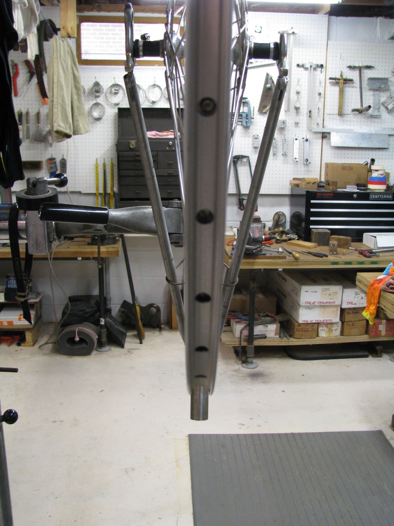
This is an attempt to show the sighting lines to check for tilt. The camera is too close to show the sides of the ST on either side of the rim.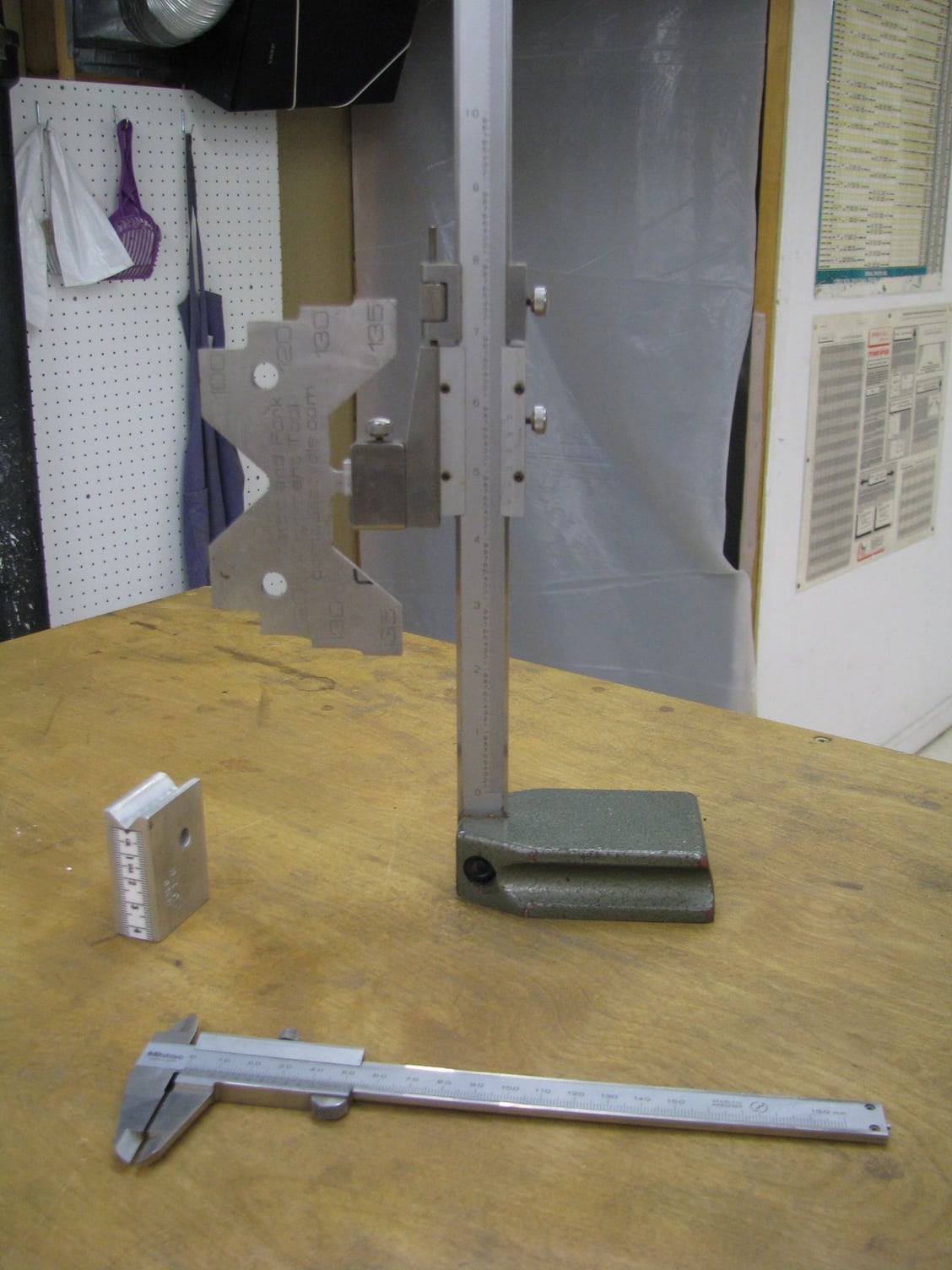
My height gage with the V and drop out width gage. The home made string test gage is on the left and of course a caliper.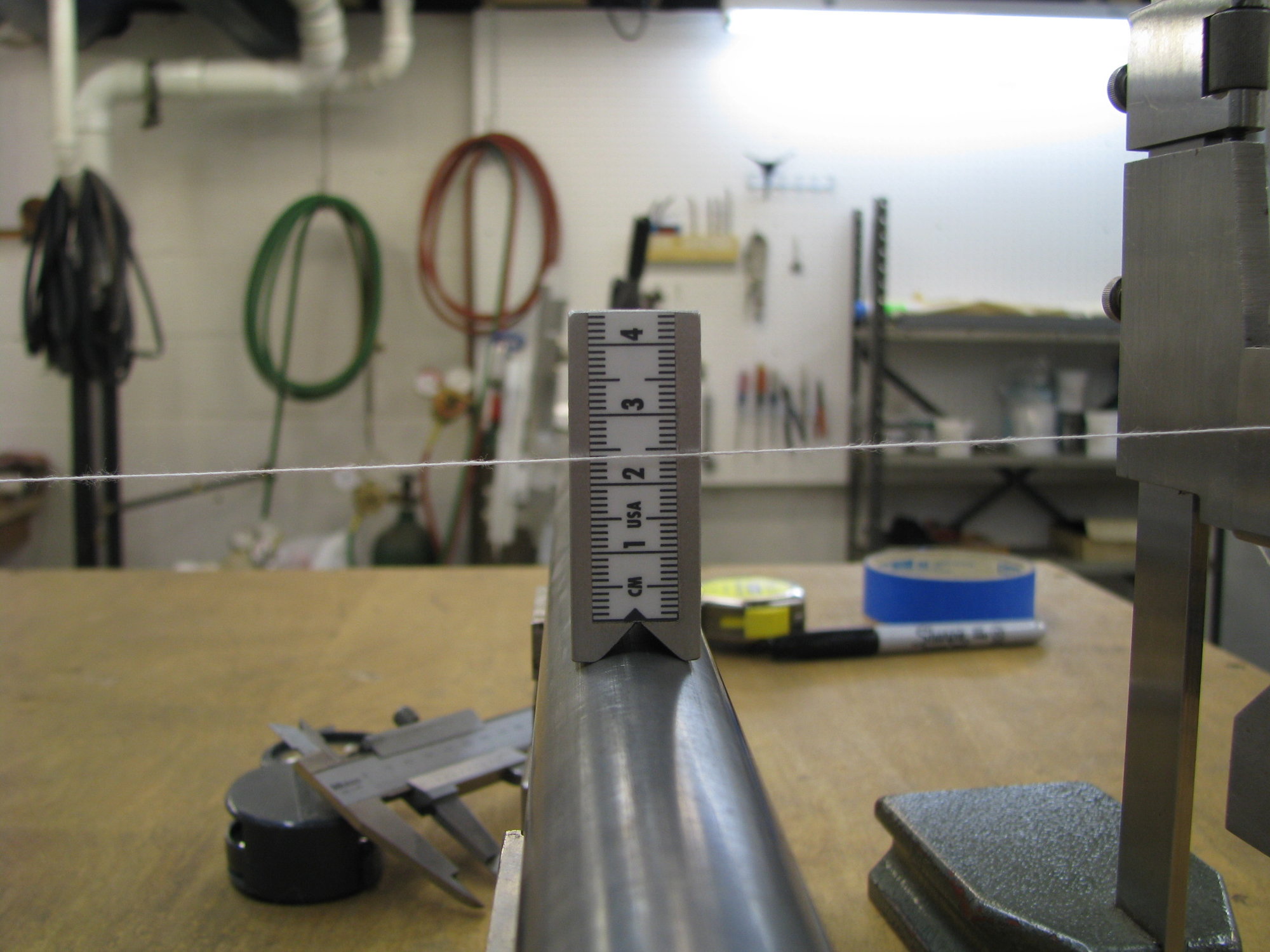
The string test gage in use. It's only a recorder of the string's relative distance off the seat tube so the rule isn't zeroed at any actual point. I like making tools that have no "precision" to them but work well. As mentioned one could use a caliper or other marked gage for this.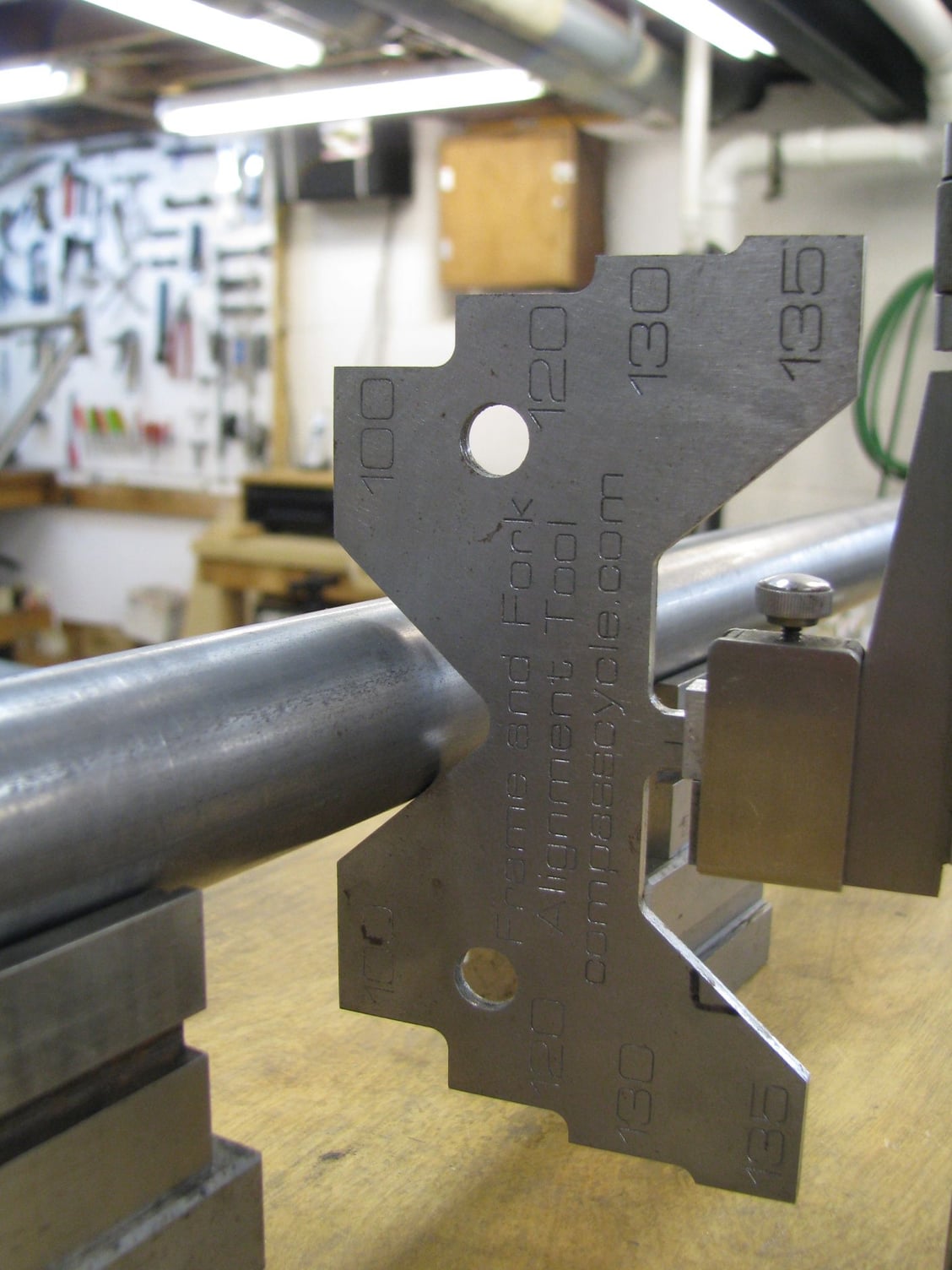
A close up of the V/dropout width gage. Center the V on the ST and move to the drop outs and see how the edges line up with the DO inner faces. A version of this is available at https://www.compasscycle.com/shop/co...lignment-tool/
This post isn't quite as complete as I wanted. I will add to it in time. When I get around to the fork alignment I will do a better job. Andy
__________________
AndrewRStewart
AndrewRStewart
12-06-18, 04:30 PM
#12
Senior Member

Join Date: Jul 2006
Location: San Jose (Willow Glen) Ca
Posts: 9,849
Bikes: Kirk Custom JK Special, '84 Team Miyata,(dura ace old school) 80?? SR Semi-Pro 600 Arabesque
Mentioned: 106 Post(s)
Tagged: 0 Thread(s)
Quoted: 2339 Post(s)
Liked 2,830 Times
in
1,545 Posts
How can you allign with just a flat plate? I was under the understanding (or misunderstanding as the case may be) that some builders pinned to keep alignment. Am thinking that if I ever build, rather that vicariously enjoy others builds, that I would do it with the bare minimum of stuff
__________________
Life is too short not to ride the best bike you have, as much as you can
(looking for Torpado Super light frame/fork or for Raleigh International frame fork 58cm)
Life is too short not to ride the best bike you have, as much as you can
(looking for Torpado Super light frame/fork or for Raleigh International frame fork 58cm)
 12-06-18, 04:55 PM
#13
Senior Member
Thread Starter
Join Date: Feb 2012
Location: Rochester, NY
Posts: 18,099
Bikes: Stewart S&S coupled sport tourer, Stewart Sunday light, Stewart Commuting, Stewart Touring, Co Motion Tandem, Stewart 3-Spd, Stewart Track, Fuji Finest, Mongoose Tomac ATB, GT Bravado ATB, JCP Folder, Stewart 650B ATB
Mentioned: 0 Post(s)
Tagged: 0 Thread(s)
Quoted: 4211 Post(s)
Liked 3,881 Times
in
2,316 Posts
Pretty much using the same base methods but with different items as you align with a wheel. Pinning is to keep geometry alignment IMO, not tracking/steering alignment. Of course the two goals have overlapping processes. Any method to trap one will do so with the other. IMO it's generally understood the jig (or drafting/drawing) relates to the geometry and the surface plate to the frame's "straightness". Either one can be off and the other spot on. The goal is to have both right. Andy.
__________________
AndrewRStewart
AndrewRStewart

