A buddy had troubles with his Wahoo Elemnt, and Wahoo was nice enough to replace it. They didn't ask to have the bad one returned to them, so he gave it to me to open up and perhaps fix whatever was wrong.
Cool!
I should say that I don't know what model this is:

When the device first turns on, it can generate a couple of screens of images, with varying amounts of corruption. Here's a link to a video of the power up sequence..
https://drive.google.com/file/d/1IN8...ew?usp=sharing
It seemed like there might be a bad connection to the display that might be improved by touching up some solder joints, so it seemed reasonable to open it up and see what's inside.
Before doing that... I figured I should see whether the firmware could be updated. I assumed that Wahoo would have already instructed my friend to do this, but I looked up the process anyway. It turns out that firmware updates have to be done via the device's wi-fi connection, and without a functioning display, there wasn't a way to do this.
Okay... then let's open it up!
The back is held on by T6 screws. These screws have small o-rings under the heads to keep moisture out, which is a good sign.
With the screws out, the front and back halves look like this:

Two flex strips connect the halves.
One looks like the USB connection, while the other might be some sort of battery monitoring signals. The battery power is transfered through the spring tabs at the top end.
The electronics is largely convered with shields to contain the RF (radio frequency) energy. The smaller shield has a trace coming out that is labeled "BT/WIFI", which means this goes to the bluetooth and wi-fi antenna. There is a little coaxial connector located on the trace, presumably to make it easier to check transmitter/receiver on the production line.
On the upper left of the board is another trace and coaxial connector, with the label "GPS" nearby. It's a good guess that the GPS electronics is under the larger shield.
The flex strips from the back half use little snap connectors to mate with the front half. These are easy to remove.

on the left side of the front half are two connectors that lead to the display assembly. One uses the same style of snap connector used in the previous photo. The other flex strip connector is obscured by the foam pad stuck on top of it.

Removing the circuit board and display from the plastic housing reveals the display and associated switches and LEDs. There's not much there that a person could tinker with.

The flat flex going to the mystery connector seemed like the most likely source of troubles at this point. The flex strip was easy to remove from the connector and didn't show any obvious damage. A mechanical pencil with 0.5mm lead is shown holding the flex strip down...

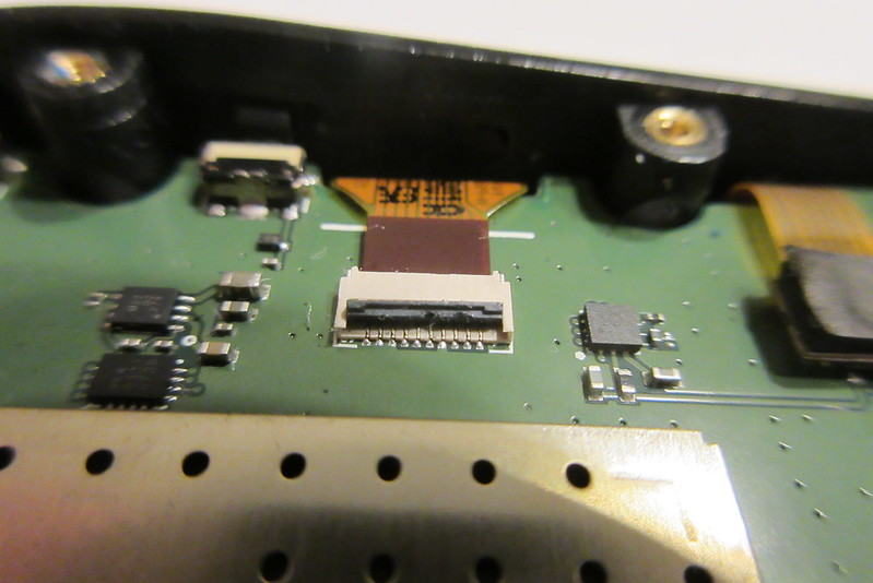
Removing the foam pad from the connector showed what appeared to be a latch in the upright position.

There does appear to be some damage to the latch, though.
I'll have to continue this in a second post...
Steve in Peoria