


DIY carbon seatpost
 11-17-21, 05:44 PM
#26
Senior Member
Join Date: Jan 2009
Location: San Diego, CA
Posts: 3,666
Mentioned: 10 Post(s)
Tagged: 0 Thread(s)
Quoted: 836 Post(s)
Liked 1,059 Times
in
743 Posts

 11-17-21, 09:47 PM
#27

Senior Member
Join Date: Feb 2012
Location: Rochester, NY
Posts: 18,063
Bikes: Stewart S&S coupled sport tourer, Stewart Sunday light, Stewart Commuting, Stewart Touring, Co Motion Tandem, Stewart 3-Spd, Stewart Track, Fuji Finest, Mongoose Tomac ATB, GT Bravado ATB, JCP Folder, Stewart 650B ATB
Mentioned: 0 Post(s)
Tagged: 0 Thread(s)
Quoted: 4197 Post(s)
Liked 3,849 Times
in
2,300 Posts
Thanks for the great details Andrew---these are exactly the kinds of things that I was hoping to discuss. I don't have the carbon tube yet, so these are characteristics I'll have to select for when buying. I'll be sure to put a length of it that I won't be using through the various tests you describe.
You're right about the clearance between the two tubes---I revised this soon after my OP. I would aim for a clearance of 0.2mm. Hopefully this can be nailed when buying the tubes, but I know a machinist or two if that fails.
The pin that you describe doesn't serve any structural role in the union of the alu insert and carbon tube; it is simply part of the clamping mechanism that I'd be stealing from the KCNC post. It's something very similar to this: https://www.schmolke-carbon.com/_ben6009/. The pin is the cross piece that the bolts to the clamp pass through.
All of the above may be moot if an insert isn't needed because the carbon tubes are apt to withstand the forces the cross piece will exert on it. Beyond empirical testing, I don't have the chops to calculate this. Even if the insert is required, it doesn't seem to me like the bond itself will be bearing much of the load. Imagine a 30mm alu section inside the top part of the linked picture. I would cut it to have the same external shape as the carbon so as to receive the arced cup and then drill the holes through the two layers. The cross piece will exert equal force on the two layers, and these will be borne by the cup that the layers butt against. The role of the bonding here would be to ensure that any small differences in the distance between the top of the hole and the arced cup won't mean that all of the load will be borne by either the alu or the carbon. Beyond these shear forces from the clamping mechanism, the continuous bending the the whole section will need to withstand might mean that a somewhat flexible resin would be most appropriate?
Rest assured that I'm riding my bike in the meantime, with a workaround for the setback issue. That's the priority, I agree!
Have fun on this project. While I understand the want to make your own stuff some here have said "don't make what you cab buy". Andy
__________________
AndrewRStewart
AndrewRStewart
11-17-21, 10:13 PM
#28
Senior Member
Join Date: Dec 2019
Location: South Shore of Long Island
Posts: 2,799
Bikes: 2010 Carrera Volans, 2015 C-Dale Trail 2sl, 2017 Raleigh Rush Hour, 2017 Blue Proseccio, 1992 Giant Perigee, 80s Gitane Rallye Tandem
Mentioned: 12 Post(s)
Tagged: 0 Thread(s)
Quoted: 1088 Post(s)
Liked 1,022 Times
in
722 Posts
Sounds like a fun idea to screw around with. Not certain the full validity of this statement but I'm under the impression that you have to be careful bonding straight carbon to aluminum due to the aluminum reacting to the carbon for some reason. From what I understand this was the reason for early aluminum lugged carbon frames failing at the joints. The solution, from what I remember, was to put a layer of fiberglass in between the two materials that served to stop the process. I believe Calfee had something about this at one time on their page since they were doing a lot of frame repairs on this style.
11-18-21, 12:51 AM
#29
Junior Member
Thread Starter
Sorry to miss understand your use of the "pin", not at all what I was taking from my reading. I've seen many posts with a top clamp inserted into the post portion and secured with a pin. I build frames and sometimes work on machinery so my take on a pin is different.
Have fun on this project. While I understand the want to make your own stuff some here have said "don't make what you cab buy". Andy
Have fun on this project. While I understand the want to make your own stuff some here have said "don't make what you cab buy". Andy
11-18-21, 01:02 AM
#30
Junior Member
Thread Starter
Love those webbed lugs on the Calfee frames btw! The classic look will always be classic, but I'm looking forward to the more organic shapes emerging from generative design---the Calfee lugs have something of that to them.
11-20-21, 11:19 AM
#31
Senior Member
Join Date: Sep 2017
Posts: 7,860
Mentioned: 38 Post(s)
Tagged: 0 Thread(s)
Quoted: 6950 Post(s)
Liked 10,958 Times
in
4,685 Posts
This experiment may end up as a great story for some lucky proctologist.
11-21-21, 05:33 PM
#32
bike whisperer

Join Date: Dec 2009
Location: Melbourne, Oz
Posts: 9,545
Bikes: https://weightweenies.starbike.com/forum/viewtopic.php?f=10&t=152015&p=1404231
Mentioned: 15 Post(s)
Tagged: 0 Thread(s)
Quoted: 1526 Post(s)
Liked 718 Times
in
510 Posts
/eyeroll @ all the naysayers
__________________
Sheldon Brown's bike info ~~~ Park Tools repair help
Half-step triple, using double gear ~~~ 6400 STI rebuild walkthrough ~~~ Want 8/9/10s @126mm OLD? OCR. ~~~ Shimano cassette body overhaul ~~~ Ergopower Escape wear repair ~~~ PSA: drivetrain wear
List of US/Canada bike co-ops ~~~ Global list
Sheldon Brown's bike info ~~~ Park Tools repair help
Half-step triple, using double gear ~~~ 6400 STI rebuild walkthrough ~~~ Want 8/9/10s @126mm OLD? OCR. ~~~ Shimano cassette body overhaul ~~~ Ergopower Escape wear repair ~~~ PSA: drivetrain wear
List of US/Canada bike co-ops ~~~ Global list
Likes For Kimmo:
11-22-21, 08:50 AM
#33
Advocatus Diaboli

Join Date: Feb 2015
Location: Wherever I am
Posts: 8,632
Bikes: Merlin Cyrene, Nashbar steel CX
Mentioned: 14 Post(s)
Tagged: 1 Thread(s)
Quoted: 4731 Post(s)
Liked 1,531 Times
in
1,002 Posts
Sounds a bit iffy. After all, we're still wondering what happened to the poor guy in this thread: https://www.bikeforums.net/bicycle-m...them-down.html
Likes For Sy Reene:
11-22-21, 06:53 PM
#34
Clark W. Griswold
Join Date: Mar 2014
Location: ,location, location
Posts: 13,493
Bikes: Foundry Chilkoot Ti W/Ultegra Di2, Salsa Timberjack Ti, Cinelli Mash Work RandoCross Fun Time Machine, 1x9 XT Parts Hybrid, Co-Motion Cascadia, Specialized Langster, Phil Wood Apple VeloXS Frame (w/DA 7400), R+M Supercharger2 Rohloff, Habanero Ti 26
Mentioned: 54 Post(s)
Tagged: 0 Thread(s)
Quoted: 4342 Post(s)
Liked 3,978 Times
in
2,659 Posts
I own a bunch of Thomson posts, would highly recommend them, have had zero problems with the 5 I own and wouldn't hesitate to buy more as needed. Quality sometimes costs a little extra but it is worth it for peace of mind.
Likes For veganbikes:
11-23-21, 10:25 AM
#35
With a mighty wind
Join Date: May 2015
Posts: 2,586
Mentioned: 13 Post(s)
Tagged: 0 Thread(s)
Quoted: 1086 Post(s)
Liked 859 Times
in
488 Posts
The seat clamp I think you are describing, needs to be fairly beefy or it might break.
I had one that style fail on its first ride. There is a lot of pressure on some fairly small areas. I suppose it�s possible to build a reinforced version but I don�t like the design.
Just fwiw, I�ve broken 2 seat posts in my time surprisingly (140lbs). I was never hurt or even wrecked but holy cow, it�s a looong way home without a seat.
11-23-21, 11:42 PM
#36
Senior Member

Join Date: Nov 2014
Location: Eugene, Oregon, USA
Posts: 27,547
Mentioned: 217 Post(s)
Tagged: 0 Thread(s)
Quoted: 18369 Post(s)
Liked 4,507 Times
in
3,350 Posts
I think my Graftek may also benefit from a 25mm seatpost if I remember right.
A couple of thoughts.
You can purchase 25mm OD, 20mm ID tubes on E-Bay.
https://www.ebay.com/itm/142615908405
That gives you 2.5mm walls or so. If that isn't enough, get a 20mm OD, 16mm ID, and epoxy it inside the 25mm.
I'm not sure the minimum epoxy gap. You can sand the tubes down slightly if needed (a sanded surface would bond better anyway).
For your "mast", calculate the length of seat post above the seat tube. I'd cut the mast part as long as practical (even all the way down to sit on the seat tube clamp). If you epoxy the mast onto your post, that will maximize the contact area.
=======================================================
@Crankycrank found a couple of 25.4mm posts. You could also calculate the inner diameter of the post. Insert an internal strengthening sleeve. And, sand the post down to 25.0mm to fit your frame.
=======================================================
You mentioned a 30.25 mm ID "mast" as being too much of a gap to shim. You can purchase 30mm OD, 25mm ID tubes that could be used for a shim. Or, 30mm OD, 26mm ID.
https://www.ebay.com/itm/143536660123
Unfortunately I fear such a configuration would be a bit unwieldy.
Nothing is cheap, and I fear that ultimately you'll be spending as much on your hack as just purchasing the more expensive finished seatpost.
Likes For CliffordK:
11-24-21, 06:45 AM
#37
Junior Member
Thread Starter
The seat clamp I think you are describing, needs to be fairly beefy or it might break.
I had one that style fail on its first ride. There is a lot of pressure on some fairly small areas. I suppose it’s possible to build a reinforced version but I don’t like the design.
Just fwiw, I’ve broken 2 seat posts in my time surprisingly (140lbs). I was never hurt or even wrecked but holy cow, it’s a looong way home without a seat.
Last edited by Jonneh; 11-24-21 at 06:54 AM.
11-24-21, 06:53 AM
#38
Junior Member
Thread Starter
Thanks for the various musings Clifford. My thoughts at the moment are leaning towards idea (1) rather than the mast idea (4) for reasons of elegance: as you say, the mast could end up quite unwieldy with all the telescoping tubes and shims. That said, depending on the failure mode of rosefart's post, the tube for (1) may have to be reinforced somewhat (perhaps with a bonded insert) or else have a decent wall thickness at the outset, which will be prudent anyway because I'm on the tall, high-leverage side.
11-24-21, 07:17 AM
#39
Junior Member
Thread Starter
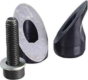
A final thing to keep in mind is the retention mechanism on the Look seatpost clamp: it uses a binding bolt similar to this one but split symmetrically. I don't think this is the best design for carbon posts, given that the compression forces are concentrated on the bolt and not spread around the circumference of the seat tube as they would be in common clamp designs, but the design was used as late as the KG 481, which was well into the era of carbon seatposts, so Look apparently gave the go-ahead. Still, another motive for a generous wall thickness!
11-25-21, 12:51 PM
#40
With a mighty wind
Join Date: May 2015
Posts: 2,586
Mentioned: 13 Post(s)
Tagged: 0 Thread(s)
Quoted: 1086 Post(s)
Liked 859 Times
in
488 Posts
It really takes some looking around to find that style of clamp. A few years ago, all the cheapie posts had them. Makes me think there have been a lot of failures.
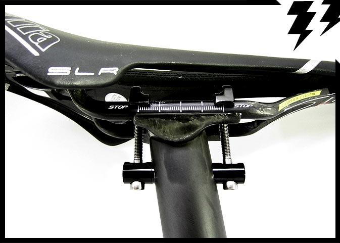
You see up top where there is the threaded aluminum bit that would clamp the top half of the seat rails? Well, right at the threads the entire piece split in half. This rendered it unfixable, either mid ride or at home.
If the entire upper section was one piece, that then had steel to thread into - exactly how Thomson does it - the design should work. It�s not the hole through the post that is the weak spot, it�s the under built clamping section.
11-26-21, 06:45 AM
#41
Junior Member
Thread Starter
I've got some 2.5mm-walled carbon tube on the way, with which I'll fashion a saucer to fit the KCNC cup (no reinforcements for the time being), drill holes for the cross piece, and stress test.
A remaining variable to decide on is the angle at which the holes are drilled. The two common variants are perpendicular to the seat post and parallel to the saddle rails, shown here, respectively:
I would think that the latter places more equal stress on each hole and less bending strain on the bolts, but the former is more common, for whatever reason. EDIT: the latter does seem to be more common on newer posts.
Last edited by Jonneh; 11-26-21 at 06:59 AM.
