


Help identify controller wires
 04-03-21, 07:11 PM
#1
Junior Member
Thread Starter
Help identify controller wires
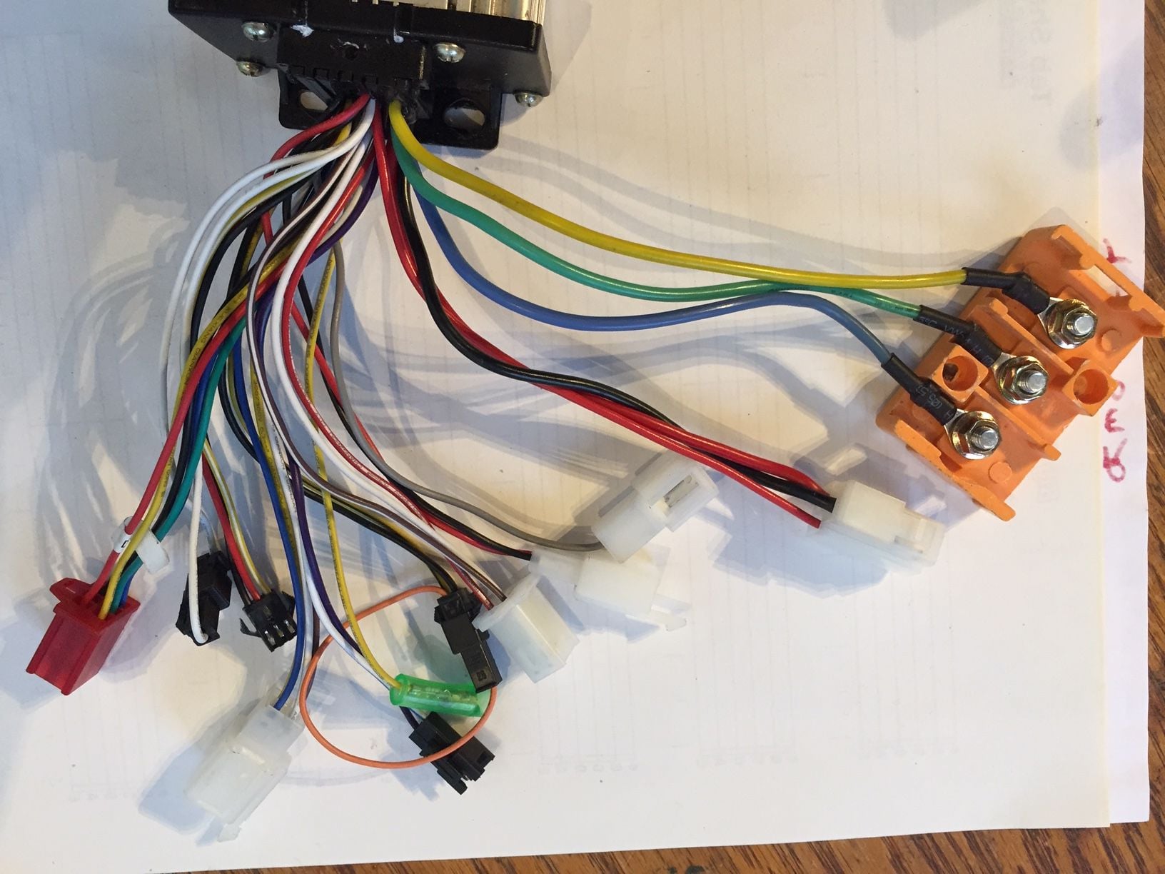
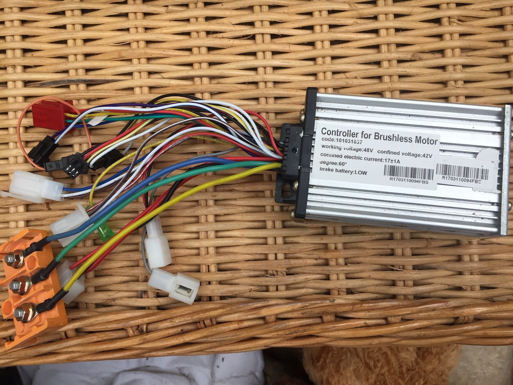
My cheap AliExpress controller died I was given this one I think it's from a proprietary bike.
I know it will not work with my LCD as long as I can get it to work with a switch or something.
My geared hub wheel has 8 HAL wires.
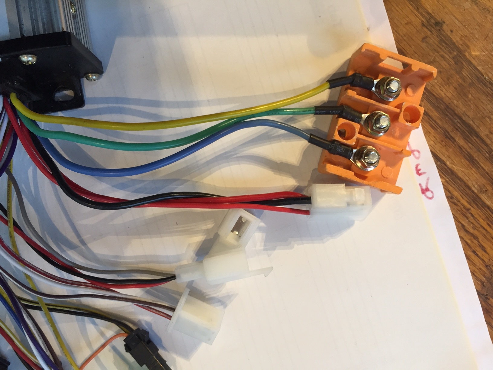
The 3 Phase wires are easy to identify not sure about the rest.
48 Volt Battery, bottom picture is LCD


I know it will not work with my LCD as long as I can get it to work with a switch or something.
My geared hub wheel has 8 HAL wires.
The 3 Phase wires are easy to identify not sure about the rest.
48 Volt Battery, bottom picture is LCD
Last edited by Bigbadjohn; 04-03-21 at 07:18 PM.
 04-03-21, 08:25 PM
#2
Senior Member
Join Date: Jul 2015
Location: Chicago Suburbs
Posts: 1,406
Bikes: GT Transeo & a half dozen ebike conversions.
Mentioned: 5 Post(s)
Tagged: 0 Thread(s)
Quoted: 340 Post(s)
Liked 275 Times
in
192 Posts
Big Bad John, You're doing it to yourself again.
I believe the orange connector with five wires is your phase wire connector,
The rest is yikes. I would suppose the white connector with thick red/black and a thine red is the plus/minus battery connector, The thin red is likely strapped to the positive to power up the controller.
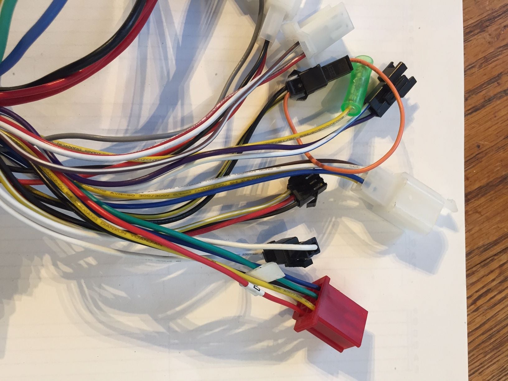
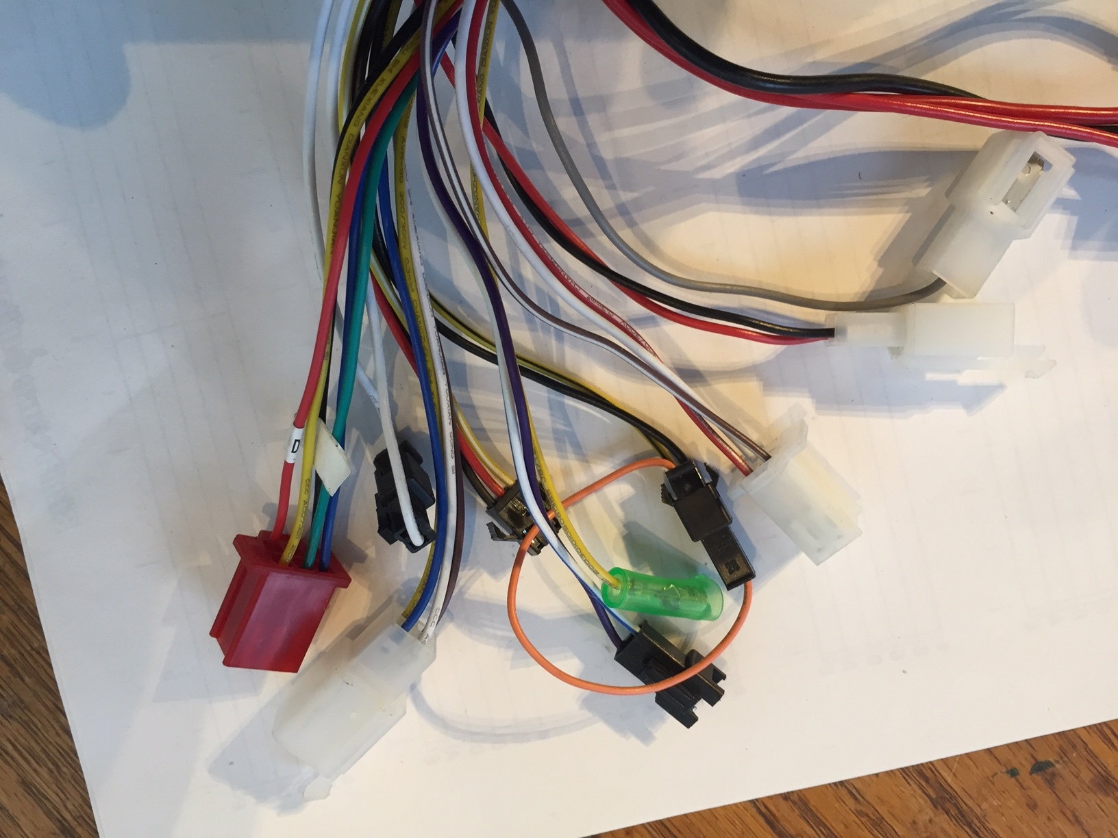
A display will need a 4 or 5 pin connector, and there are none? So no display and then there would be a power level switch, which I know nothing about. Two wire connectors are either brakes or lights. Three wire connectors could be throttle or pedal assist or that power setting. Happy guessing.
If the controller powers up, you should find out which wire in those three pin connectors is ground and then get the voltages on the other two, That might tell you what connector is for throttle.
I believe the orange connector with five wires is your phase wire connector,
The rest is yikes. I would suppose the white connector with thick red/black and a thine red is the plus/minus battery connector, The thin red is likely strapped to the positive to power up the controller.
A display will need a 4 or 5 pin connector, and there are none? So no display and then there would be a power level switch, which I know nothing about. Two wire connectors are either brakes or lights. Three wire connectors could be throttle or pedal assist or that power setting. Happy guessing.
If the controller powers up, you should find out which wire in those three pin connectors is ground and then get the voltages on the other two, That might tell you what connector is for throttle.
Likes For Doc_Wui:
04-03-21, 09:30 PM
#3
Junior Member
Thread Starter
I know I am a glutton for punishment.
Thanks again Doc_Wui what would I do without you , I did it again plugged in the battery wrong polarity I guess most controller are not fused.
I have been trying to find a controller that will work with my LCD not having any success. In the meantime would like to get this one working.
That's actually all I want full power all the time with a simple switch to turn it on, I only have a twist throttle no peddle.
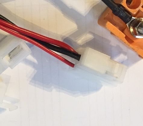
So there are 3 wires on the power plug 2 red and a black when I connect the 2 reds together it powers on, so I would need a switch to do that is that how it works?
"The thin red is likely strapped to the positive to power up the controller." I have a switch on my battery I could use to turn on with 2 reds connected.
It looks like the 5 wire red connector is the HAL
is my LCD standard as I can't find a controller to accept it I dont want to buy another combo I already have 3 LCD's
Your help is greatly appreciated
John
Thanks again Doc_Wui what would I do without you , I did it again plugged in the battery wrong polarity I guess most controller are not fused.
I have been trying to find a controller that will work with my LCD not having any success. In the meantime would like to get this one working.
That's actually all I want full power all the time with a simple switch to turn it on, I only have a twist throttle no peddle.
So there are 3 wires on the power plug 2 red and a black when I connect the 2 reds together it powers on, so I would need a switch to do that is that how it works?
"The thin red is likely strapped to the positive to power up the controller." I have a switch on my battery I could use to turn on with 2 reds connected.
It looks like the 5 wire red connector is the HAL
is my LCD standard as I can't find a controller to accept it I dont want to buy another combo I already have 3 LCD's
Your help is greatly appreciated
John
Last edited by Bigbadjohn; 04-03-21 at 09:37 PM.
04-04-21, 06:58 AM
#4
Senior Member
Join Date: Jul 2014
Location: socal
Posts: 4,262
Mentioned: 9 Post(s)
Tagged: 0 Thread(s)
Quoted: 882 Post(s)
Liked 821 Times
in
620 Posts
Aren't there relatively inexpensive, self-learning controllers that can be connected, power administered, then the "learning" wire cut and the system is operational I've never needed to explore since I purchased kits.
04-04-21, 10:56 AM
#5
Junior Member
Thread Starter
Yes but I would like one that connects to my LCD (last picture) that came in a cheap kit, not sure if it's a standard LCD or there is a standard for LCD's or Analysts
Thanks
Thanks
04-04-21, 11:40 AM
#6
Senior Member
Join Date: Jul 2014
Location: socal
Posts: 4,262
Mentioned: 9 Post(s)
Tagged: 0 Thread(s)
Quoted: 882 Post(s)
Liked 821 Times
in
620 Posts
Maybe you could purchase one in which the LCD area is identified. Then, when you set everything up, you could connect the LCD. Shouldn't be dangerous if you get it wrong (IDT, but I'm a Chemist so could be very wrong) since it draws only five or so amps. If the wires are wrong, try a different combination. Just a guess since I've never done it. DW is the expert.
 04-05-21, 01:51 PM
#8
Senior Member
Join Date: Jul 2014
Location: socal
Posts: 4,262
Mentioned: 9 Post(s)
Tagged: 0 Thread(s)
Quoted: 882 Post(s)
Liked 821 Times
in
620 Posts
I'm out of my element now, and wouldn't recommend that. If DW can't help, you might try endless sphere. There are individuals there who do all sorts of conversions.
Likes For 2old:
04-05-21, 06:50 PM
#9
Junior Member
Thread Starter
Thanks I am sure you are correct, I saw a YouTube a few months ago and that's how they did it
there are so many controllers and all are different.
When you think about it there are only 3 wires, and you know what would happen if you connected the red and black 48V, so it must be the 2 reds.
Very good video
there are so many controllers and all are different.
When you think about it there are only 3 wires, and you know what would happen if you connected the red and black 48V, so it must be the 2 reds.
Very good video
Last edited by Bigbadjohn; 04-05-21 at 08:21 PM.
Likes For Bigbadjohn:
04-06-21, 01:24 PM
#10
Junior Member
Thread Starter
I hooked up the unidentified controller wires t matched up good the only thing I could not determine throttle so left it, tried one got sparks
I connected original one not the same one I plugged backwards thats as dead as a DoDo
could not get it to work motor made different noises for different HAL configuration.
I unplugged all the HAL wires and bike works, so maybe one of the HAL wire connections was not making contact. I will check and try again
I don't think it does any hard without
it worked lifting the wheel up when I took it for a ride it made clunky noise I connected HAL again now it runs smooth.
Was riding up a long steep hill yesterday with headwind blew everything BMS, Controller, hopefully not the motor
Last edited by Bigbadjohn; 04-11-21 at 06:40 PM. Reason: g
