


Wahoo Kickr Circuit Board Repair
 02-23-23, 12:26 PM
#101


Randomhead
Join Date: Aug 2008
Location: Happy Valley, Pennsylvania
Posts: 24,392
Mentioned: 0 Post(s)
Tagged: 0 Thread(s)
Quoted: 4 Post(s)
Liked 3,693 Times
in
2,515 Posts
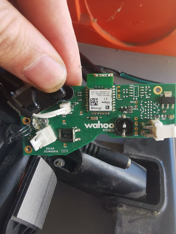
The boards between the trainers are not the same. At some point they went from an NPN braking transistor to a PNP braking transistor. My guess is that PNP worked better in their circuit. It seems like it would be really lucky if the same firmware would work for both. But it's not impossible. Otherwise every board I have seen a picture of looks nearly identical, including the bike.
 02-23-23, 12:40 PM
#102
Randomhead
Join Date: Aug 2008
Location: Happy Valley, Pennsylvania
Posts: 24,392
Mentioned: 0 Post(s)
Tagged: 0 Thread(s)
Quoted: 4 Post(s)
Liked 3,693 Times
in
2,515 Posts


 02-23-23, 12:43 PM
#103
Randomhead
Join Date: Aug 2008
Location: Happy Valley, Pennsylvania
Posts: 24,392
Mentioned: 0 Post(s)
Tagged: 0 Thread(s)
Quoted: 4 Post(s)
Liked 3,693 Times
in
2,515 Posts
We need someone to smoke a v6 so we can see how the ethernet works. /s
02-23-23, 05:18 PM
#104
Newbie
Join Date: Feb 2023
Posts: 9
Mentioned: 0 Post(s)
Tagged: 0 Thread(s)
Quoted: 2 Post(s)
Likes: 0
Liked 1 Time
in
1 Post
unterhausen and others. If I purchase the Gem2 development board from north pole engineering, what is the correct wiring layout? Feel pretty confident I can get the firmware off the original chip. Just wainting for the ST-Link v2 to arrive.
Cheers, Simon
02-25-23, 07:20 PM
#105
Randomhead
Join Date: Aug 2008
Location: Happy Valley, Pennsylvania
Posts: 24,392
Mentioned: 0 Post(s)
Tagged: 0 Thread(s)
Quoted: 4 Post(s)
Liked 3,693 Times
in
2,515 Posts
I believe the development kit modules from the link I provided have the same pinout as the wahoo.
It seems to me that your board has other issues, I'm not clear on what it would take to get it running again.
It seems to me that your board has other issues, I'm not clear on what it would take to get it running again.
02-27-23, 11:48 PM
#106
Newbie
Join Date: Jul 2022
Posts: 15
Mentioned: 3 Post(s)
Tagged: 0 Thread(s)
Quoted: 9 Post(s)
Likes: 0
Liked 3 Times
in
3 Posts
Hey pixjnr , the gem2 from North Pole should be the same pinout, you will just need to swap the firmware over from your old chip. However you will probably pay a ton for postage to aus from north pole. An ST-Link should work, but I converted mine to a J-link because it was slightly easier to work with the software. I have been trialling changing over the nrf52832 onto the faulty module using a hot-plate solder setup which seems to work better than hot air.
I would say your voltage regulator will likely be damaged as well and maybe the control transistor.
I can have a look at it for you, or talk you through any repairs you try yourself
I would say your voltage regulator will likely be damaged as well and maybe the control transistor.
I can have a look at it for you, or talk you through any repairs you try yourself
03-02-23, 04:12 AM
#107
Newbie
Join Date: Feb 2023
Posts: 9
Mentioned: 0 Post(s)
Tagged: 0 Thread(s)
Quoted: 2 Post(s)
Likes: 0
Liked 1 Time
in
1 Post
Thanks rogers2000 . Might be great to have a chat. Can you PM me your details? I've got the J Link & ST Vlink2 and NRF aliexpress chip now. In your earlier reply you indicated where to connect SWD, Data and Ground for downloading the chip firmware via Jlink and doing so insitu. Where do i connect the 3.3V VCC from the Jlink or ST LINK to the board?
Where on the board are the voltage regulator and control resistor? When can I purchase these from?
I just googled hot plate solder. Never knew this. Hmm, something else to buy!!
I think this might just be above my tech ability - but I do love learning. If i get stuck, I think I would be up for sending the board to you.
Cheers, Pix.
03-06-23, 11:18 AM
#109
Randomhead
Join Date: Aug 2008
Location: Happy Valley, Pennsylvania
Posts: 24,392
Mentioned: 0 Post(s)
Tagged: 0 Thread(s)
Quoted: 4 Post(s)
Liked 3,693 Times
in
2,515 Posts
I don't know if the dev board would be useful to you. I think it's mostly a way to mechanically access the module
It's cheap though, isn't it?
We need to crowd-source a schematic and BOM for these boards.
It's cheap though, isn't it?
We need to crowd-source a schematic and BOM for these boards.
Last edited by unterhausen; 03-06-23 at 11:29 AM.
03-07-23, 10:41 AM
#110
Newbie
Join Date: Mar 2023
Posts: 3
Mentioned: 0 Post(s)
Tagged: 0 Thread(s)
Quoted: 0 Post(s)
Likes: 0
Liked 2 Times
in
2 Posts
rogers2000 Could you be so kind to make litlle video(short tutorial) with extracting firmware? )
Got problem with incorrect power as well, afraid to do smth wrong..
Got problem with incorrect power as well, afraid to do smth wrong..
Last edited by Alex0; 03-07-23 at 10:51 AM.
Likes For Alex0:
03-08-23, 01:26 PM
#111
Randomhead
Join Date: Aug 2008
Location: Happy Valley, Pennsylvania
Posts: 24,392
Mentioned: 0 Post(s)
Tagged: 0 Thread(s)
Quoted: 4 Post(s)
Liked 3,693 Times
in
2,515 Posts
Welcome to the forum, a video would be nice. I just bought a J-link
I just ordered some gem2 modules. I was tempted to get some gem 3 modules, but controlled myself
I just ordered some gem2 modules. I was tempted to get some gem 3 modules, but controlled myself
Last edited by unterhausen; 03-08-23 at 01:38 PM.
03-13-23, 11:36 AM
#112
Randomhead
Join Date: Aug 2008
Location: Happy Valley, Pennsylvania
Posts: 24,392
Mentioned: 0 Post(s)
Tagged: 0 Thread(s)
Quoted: 4 Post(s)
Liked 3,693 Times
in
2,515 Posts
I got the dev kit. It has 2 gem2 modules and a third soldered onto a usb interface. I'm not sure what I'm going to do with it. I was hoping to find some software support. I can't imagine I'm the first non-oem to buy one.
Interestingly, it has Wahoo branding all over it.
It shows up as a comm port when I plug it in, I wonder what commands it responds to. The serial port is used to talk to a controller under normal use. The only chips on the board are the off-brand usb to serial and possibly some kind of serial memory. Didn't get out the microscope yet
Apparently bluetooth and Ant+ are handled by Nordic libraries. Nordic has a lot of development tools.
Okay, they sent me a link to the development resources and they are pretty impressive. Not really germane to this thread though. Although possibly the programming utilities would be good, either from NPE or Nordic
Last edited by unterhausen; 03-14-23 at 10:40 AM.
03-19-23, 10:19 AM
#115
Randomhead
Join Date: Aug 2008
Location: Happy Valley, Pennsylvania
Posts: 24,392
Mentioned: 0 Post(s)
Tagged: 0 Thread(s)
Quoted: 4 Post(s)
Liked 3,693 Times
in
2,515 Posts
It's working for me, thanks. You use the segger jlink programs? I guess there is some messing around required to use them with a clone.
Last edited by unterhausen; 03-19-23 at 10:24 AM.
03-28-23, 12:04 PM
#116
Newbie
Join Date: Mar 2023
Posts: 3
Mentioned: 0 Post(s)
Tagged: 0 Thread(s)
Quoted: 0 Post(s)
Likes: 0
Liked 2 Times
in
2 Posts
Thanks a lot to rogers2000 for helping with commands & adress! Repired my trainer with it, but in first attempt from first one notebook binfiles not loaded correctly, from second one loaded properly). solded gem2 module by north pole
Likes For Alex0:
03-31-23, 09:43 AM
#117
Randomhead
Join Date: Aug 2008
Location: Happy Valley, Pennsylvania
Posts: 24,392
Mentioned: 0 Post(s)
Tagged: 0 Thread(s)
Quoted: 4 Post(s)
Liked 3,693 Times
in
2,515 Posts
Welcome to the forum, what happened to your trainer that you had to replace the module?
04-09-23, 08:30 PM
#119
Newbie
Join Date: Apr 2023
Posts: 2
Mentioned: 0 Post(s)
Tagged: 0 Thread(s)
Quoted: 0 Post(s)
Likes: 0
Liked 0 Times
in
0 Posts
This was very helpful and I was able to reprogram another GEM2 chip which I got from North Pole Engineering. Unfortunately it appears something else is wrong as I still have no speed/cadence. Wondering if you have ideas to help troubleshoot further. I've checked the regulator and voltage looks proper but the output of the speed sensor stays at 0V when connected to the board. Just to try I de-soldered the wire going to the main board from the speed sensor and the output works exactly as expected in your video. So it seems something is bringing the output down to 0V permanently and I can't quite track it down. Any suggestions?
04-09-23, 11:39 PM
#120
Newbie
Join Date: Jul 2022
Posts: 15
Mentioned: 3 Post(s)
Tagged: 0 Thread(s)
Quoted: 9 Post(s)
Likes: 0
Liked 3 Times
in
3 Posts
That sounds like a frustrating problem, I haven't looked at the sensor circuit in detail, my best guess is it is a simple IR RX/TX pair. The RX is prob a simple IR transistor that activates with any IR light which turns on a digital out, being 5v. You can see which one is the TX by observing a small red light through your cellphone camera. If there is 5v when it is not connected to the GEM2, and this drops to 0V when connected, then the fault could be the GEM2, a shorted track, or a faulty RX transistor. I would connect it to a bench top power supply and observe the current draw when the sensor is connected and disconnected. This would guide me to my next move, if there is a large current draw then this would indicate a short, I would crank the voltage up to maybe around 300-600mA for a short period and try and locate what area is getting warm.
once you are happy the sensor is alternating between 0v and 5v with a reflector, it still won't show cadence in the app unless the sensor is alternating extremely fast, i.e. you prob need to assemble it back together and spin the flywheel, it is very hard to register by hand only
once you are happy the sensor is alternating between 0v and 5v with a reflector, it still won't show cadence in the app unless the sensor is alternating extremely fast, i.e. you prob need to assemble it back together and spin the flywheel, it is very hard to register by hand only
Last edited by rogers2000; 04-09-23 at 11:50 PM. Reason: further info
04-13-23, 11:08 AM
#121
Newbie
Join Date: Apr 2023
Posts: 5
Mentioned: 1 Post(s)
Tagged: 0 Thread(s)
Quoted: 3 Post(s)
Likes: 0
Liked 0 Times
in
0 Posts
Hello, I bought a broken wahoo v1(maybe) in hopes of fixing it (can't afford a new one).
I am in the US atm for work and am planning to order a NorthPole module here. NorthPole sell both GEM1 and GEM2 module.
The issue is that I don't know which version of the kickr it is. From looking at it briefly it does not seem to have LEDs on the Kickr shell but all the PCB in this thread seem to have indicator LEDs.
The question then is do all Kickrs' use the GEM2 module or is there a version which uses the GEM1?
04-13-23, 11:54 AM
#123
Newbie
Join Date: Apr 2023
Posts: 5
Mentioned: 1 Post(s)
Tagged: 0 Thread(s)
Quoted: 3 Post(s)
Likes: 0
Liked 0 Times
in
0 Posts
Ok, further digging, looks like the kickr version 1 used the GEM1 module. Please correct me if the following deduction is incorrect
The FCC ID, IC and Model for the bluetooth module wahoo presents to the FCC in 2015 is the same as the ones on the picture NorthPole has on their webste for the GEM1 module.
I think it is fair to assume within reason that the modules are the same.
store.npe-inc.com / gem1-oem-module
fccid.io / PADWF111 / Users-Manual / Users-Manual-2733339
(remove spaces between slashes to access link)
04-13-23, 12:02 PM
#124
Newbie
Join Date: Apr 2023
Posts: 2
Mentioned: 0 Post(s)
Tagged: 0 Thread(s)
Quoted: 0 Post(s)
Likes: 0
Liked 0 Times
in
0 Posts
That sounds like a frustrating problem, I haven't looked at the sensor circuit in detail, my best guess is it is a simple IR RX/TX pair. The RX is prob a simple IR transistor that activates with any IR light which turns on a digital out, being 5v. You can see which one is the TX by observing a small red light through your cellphone camera. If there is 5v when it is not connected to the GEM2, and this drops to 0V when connected, then the fault could be the GEM2, a shorted track, or a faulty RX transistor. I would connect it to a bench top power supply and observe the current draw when the sensor is connected and disconnected. This would guide me to my next move, if there is a large current draw then this would indicate a short, I would crank the voltage up to maybe around 300-600mA for a short period and try and locate what area is getting warm.
once you are happy the sensor is alternating between 0v and 5v with a reflector, it still won't show cadence in the app unless the sensor is alternating extremely fast, i.e. you prob need to assemble it back together and spin the flywheel, it is very hard to register by hand only
once you are happy the sensor is alternating between 0v and 5v with a reflector, it still won't show cadence in the app unless the sensor is alternating extremely fast, i.e. you prob need to assemble it back together and spin the flywheel, it is very hard to register by hand only
However now I'm running into the issue of erratic and fluctuating power. As in during a Zwift ride the magnetic brake will keep coming in and out almost like a bad PID feedback loop. The power number jump all over the place too when keeping constant cadence and spindowns don't seem to help either. In fact for some reason the factory spindown keeps failing now.
04-14-23, 10:05 AM
#125
Randomhead
Join Date: Aug 2008
Location: Happy Valley, Pennsylvania
Posts: 24,392
Mentioned: 0 Post(s)
Tagged: 0 Thread(s)
Quoted: 4 Post(s)
Liked 3,693 Times
in
2,515 Posts
Welcome to the forum.
Sure looks like it, I wish you had posted this before I ordered my Gem2 modules. Now I might have to get a Gem3 dev kit too to complete the set. It makes sense that they would have used a Gem1 since I'm pretty sure the original kickr was their first product.
Sure looks like it, I wish you had posted this before I ordered my Gem2 modules. Now I might have to get a Gem3 dev kit too to complete the set. It makes sense that they would have used a Gem1 since I'm pretty sure the original kickr was their first product.