


Frame jig headtube cones and bottom bracket fixture.
 12-26-22, 10:06 PM
#1
Newbie
Thread Starter
Join Date: Oct 2022
Posts: 4
Mentioned: 0 Post(s)
Tagged: 0 Thread(s)
Quoted: 1 Post(s)
Likes: 0
Liked 1 Time
in
1 Post
Frame jig headtube cones and bottom bracket fixture.
Hey everyone,
I'm from Australia and am making my first frame and am looking to make a jig. I've got most of it figured using aluminium extrusion, inspired by a lot of designs I've seen on the internet.
I can't seem to find anywhere to buy the headset cones or the bottom bracket fixture online.
Does anyone know where I can get some?
or readily available parts that could be used in their place?
I don't have access to a metal lathe so can't machine them myself.
I do have a wood lathe though, If I made them from hardwood do you think they would hold up for a single frame? I sure I could figure out something else to use as a heat sink.
thanks for any advice,
Cheer Ryan
 12-27-22, 05:41 AM
#2
Senior Member
Join Date: Jan 2013
Location: South Jersey
Posts: 2,262
Mentioned: 18 Post(s)
Tagged: 0 Thread(s)
Quoted: 713 Post(s)
Liked 796 Times
in
473 Posts
I'd make then for you, but shipping to Australia would make them quite expensive. I've done it before and the shipping almost doubled the cost. If you are TIG welding, hardwood would probably last a very long time. If you are brazing, they might get charred a bit, but would probably still hold up for a while.
12-27-22, 06:52 AM
#3

framebuilder
When I make a lugged frame, I leave the head tube sticking out beyond the top of the head lug and bottom of the down tube lug an extra 20 to 25mm. This has 2 advantages, 1st that tube sticking out is where you can dump any extra silver as you are brazing the lug to get really clean shorelines. 2nd it allows extra length that can be used for alignment checking.
Because the tubes are sticking out beyond the lug, it won't be a problem burning the wood cones when just spot brazing the tubes together. The flame/heat won't be that close to the wood. If you want to be extra cautious you can stick the head tube even father out from the lugs.
By the way, the way I braze a frame is to only spot the frame in the fixture and braze each joint free outside of the fixture after checking alignment after spotting. The picture of the fluxed frame in the fixture was just for a picture so i could show the lug more clearly. More flux than that is applied where the spot is made.
Doug Fattic
Niles, Michigan

spotting in the fixture

final alignment check before cutting off the extra head tube length
Because the tubes are sticking out beyond the lug, it won't be a problem burning the wood cones when just spot brazing the tubes together. The flame/heat won't be that close to the wood. If you want to be extra cautious you can stick the head tube even father out from the lugs.
By the way, the way I braze a frame is to only spot the frame in the fixture and braze each joint free outside of the fixture after checking alignment after spotting. The picture of the fluxed frame in the fixture was just for a picture so i could show the lug more clearly. More flux than that is applied where the spot is made.
Doug Fattic
Niles, Michigan
spotting in the fixture
final alignment check before cutting off the extra head tube length
12-27-22, 08:43 AM
#4
Senior Member
Join Date: Dec 2019
Posts: 953
Mentioned: 3 Post(s)
Tagged: 0 Thread(s)
Quoted: 321 Post(s)
Liked 263 Times
in
212 Posts
Yes you can make them out of wood. They get singed a bit but it's OK.
I now do have a mini lathe so made some nice aluminum ones But the wooden ones were fine. I posted some pictures of them before here:
https://www.bikeforums.net/21898214-post30.html
I now do have a mini lathe so made some nice aluminum ones
But the wooden ones were fine. I posted some pictures of them before here:https://www.bikeforums.net/21898214-post30.html
12-27-22, 09:43 AM
#5


Randomhead
Join Date: Aug 2008
Location: Happy Valley, Pennsylvania
Posts: 24,385
Mentioned: 0 Post(s)
Tagged: 0 Thread(s)
Quoted: 4 Post(s)
Liked 3,686 Times
in
2,509 Posts
I would ask Paul Ketelaar if he would help you with this.
Likes For unterhausen:
12-27-22, 10:44 AM
#6
Senior Member
Join Date: Feb 2012
Location: Rochester, NY
Posts: 18,054
Bikes: Stewart S&S coupled sport tourer, Stewart Sunday light, Stewart Commuting, Stewart Touring, Co Motion Tandem, Stewart 3-Spd, Stewart Track, Fuji Finest, Mongoose Tomac ATB, GT Bravado ATB, JCP Folder, Stewart 650B ATB
Mentioned: 0 Post(s)
Tagged: 0 Thread(s)
Quoted: 4194 Post(s)
Liked 3,837 Times
in
2,295 Posts
I have found that developing area contacts for various needs to be very beneficial. From metal work that you don't have the tools for (lathe, mill) to sources for scraps/cut offs to play with or services like paint and sandblasting having a near by network makes stuff happen easier. Local schools, machine shops, art studios, auto collusion shops are all possible contacts. We have a hobby shop in town that I have had their guys, or people they know, help me out.
I see jig cones offered on the USA EBay site pretty often. Many are described as motorcycle jig parts, not bicycle stiff.
Also like Doug I like to have a bit of extra head tube (and seat tube at the top) extend beyond ends. Andy
I see jig cones offered on the USA EBay site pretty often. Many are described as motorcycle jig parts, not bicycle stiff.
Also like Doug I like to have a bit of extra head tube (and seat tube at the top) extend beyond ends. Andy
__________________
AndrewRStewart
AndrewRStewart
12-27-22, 08:02 PM
#7
blahblahblah chrome moly

Join Date: Apr 2009
Location: Seattle
Posts: 1,984
Mentioned: 92 Post(s)
Tagged: 0 Thread(s)
Quoted: 1172 Post(s)
Liked 2,566 Times
in
1,072 Posts
I've admired Alex Meade's stuff from afar, haven't bought or tried any. I thought he used to show cones as a standard item but now he only shows them under the heading of Custom tooling:
https://alexmeadetools.com/product/custom-tooling/
I have a lathe and make my own cones, but I'm not really set up to make them for other people at the moment.
https://alexmeadetools.com/product/custom-tooling/
I have a lathe and make my own cones, but I'm not really set up to make them for other people at the moment.
Likes For bulgie:
12-27-22, 09:01 PM
#8
Senior Member
Join Date: Feb 2012
Location: Rochester, NY
Posts: 18,054
Bikes: Stewart S&S coupled sport tourer, Stewart Sunday light, Stewart Commuting, Stewart Touring, Co Motion Tandem, Stewart 3-Spd, Stewart Track, Fuji Finest, Mongoose Tomac ATB, GT Bravado ATB, JCP Folder, Stewart 650B ATB
Mentioned: 0 Post(s)
Tagged: 0 Thread(s)
Quoted: 4194 Post(s)
Liked 3,837 Times
in
2,295 Posts
I will second the suggestion of Alex Meade's stuff. I have a bunch of tools by him, including a few custom ones. But the shipping to Australia aspect would remain.
frame jig cones for sale | eBay Here's the link to current offers. I note that there's an India seller (although their cones look really rough). Andy
frame jig cones for sale | eBay Here's the link to current offers. I note that there's an India seller (although their cones look really rough). Andy
__________________
AndrewRStewart
AndrewRStewart
Likes For Andrew R Stewart:
01-05-23, 02:37 PM
#9
Newbie
I bought a set of these for my jig. https://www.chopsource.com/bicycle-f...set-steel.html
Here is a pic.

Here is a pic.
01-07-23, 11:15 PM
#10
Senior Member
Join Date: Aug 2012
Location: Seattle
Posts: 507
Mentioned: 0 Post(s)
Tagged: 0 Thread(s)
Quoted: 103 Post(s)
Liked 144 Times
in
88 Posts
I bought a set of these for my jig. https://www.chopsource.com/bicycle-f...set-steel.html
Here is a pic.
Here is a pic.
__________________
https://www.flickr.com/photos/54319503@N05/
https://www.draper-cycles.com
https://www.flickr.com/photos/54319503@N05/
https://www.draper-cycles.com
01-08-23, 07:50 AM
#11
Randomhead
Join Date: Aug 2008
Location: Happy Valley, Pennsylvania
Posts: 24,385
Mentioned: 0 Post(s)
Tagged: 0 Thread(s)
Quoted: 4 Post(s)
Liked 3,686 Times
in
2,509 Posts
Doesn't bikecad give arctos measurements? I suppose this isn't quite an arctos style fixture.
My fixture measures everything from the bb center. When I built it, I saw some fixtures that have a virtual fork, so I built it that way. So you set up the "fork" and the wheelbase and the fixture setup is done. But I have never gotten it set up to measure that way. Mostly because I always have extra head tube at the bottom. So it's all off a little and I haven't quite figured out how to accommodate that.
My fixture measures everything from the bb center. When I built it, I saw some fixtures that have a virtual fork, so I built it that way. So you set up the "fork" and the wheelbase and the fixture setup is done. But I have never gotten it set up to measure that way. Mostly because I always have extra head tube at the bottom. So it's all off a little and I haven't quite figured out how to accommodate that.
01-08-23, 02:45 PM
#12
blahblahblah chrome moly
Join Date: Apr 2009
Location: Seattle
Posts: 1,984
Mentioned: 92 Post(s)
Tagged: 0 Thread(s)
Quoted: 1172 Post(s)
Liked 2,566 Times
in
1,072 Posts
There are jigs that let you "design the frame" right there on the jig, and the jig more or less calculates the heattube length and height for you. Doug Fattic's laser-cut jig comes to mind as an example. A BM Hydra is another. But if you don't have that, you gotta trust your drawing or CAD program to give you all the tube lengths and angles, then you just carefully set the angles and trust that the tube miters wouldn't line up unless the HT is at the correct height.
Since there's some tolerance in every measurement and the tolerances stack up, the bottom of the HT might be a little off this way, but with care you should be able to get it within say a mm or two. Plenty precise enough for most uses especially if the TT slopes at all (I mean, on purpose!) If you're shooting for a level TT, then a couple mm off might be noticeable.
Story time, kids! When I started at Davidson in '84, he was (IMHO) insanely focused on the TT being perfectly level. He'd make the front triangle, cut the HT to length (even reaming and facing), install the finished fork with a precisely-made dummy headset (13.5 mm or 15 mm lower stack as called for in the build sheet). Wheels were installed in the fork and chainstays, which weren't brazed in the BB shell yet. Then he jacked up the BB with a machinist jack until the TT was exactly level. Only then did he finalize the seatstay length and make the seatstays at the measured length. So what he was saying is, if there are errors, it was in the frame angles and/or BB height, but the TT must stay exactly level! That was on his one-off custom frames; he was a bit more "trusting" or less picky on the production models. Still, imagine doing all that for each and every custom frame, nuts!
When I took over making the custom frames, I was able to prove to Bill that, with the precision we were able to cut the miters to, with pinning the lugs and careful brazing, the TT came out level automatically. Without all that extra work of mounting wheels and jacking up the BB.
That was with a Marchetti jig with no virtual fork, so the bottom of the HT was just sort of out there in space. But later, after we got a Hydra (which does have a virtual fork), we pretty much ignored it and kept building the way we did on the Marchetti. Namely, set ST angle, HT angle, and TT angle, and confirm everything's jake by seeing if the miters both hit the HT at the correct height. This method requires you to be able to to trust your miters are done very precisely. But we always did have very exact/repeatable miters, guaranteed by our mitering setup on the mill. So, once you positioned the BB, ST, TT and HT into the jig, you'd find that the DT laid in perfectly, falling just the right distance above the bottom of the HT.
We didn't have CAD back then, just a spreadsheet with the trig calcs to give you the miter lengths, but it was very well proven by then. Math doesn't lie. Of course the spreadsheet had to have inputs for every dimension, like where does the lug position the TT and DT relative to the ends of the HT, a dimension that varies from one lug brand/model to the next. I added macros to the spreadsheet to provide you with menus for things like lug brand, headset stack, and dropout brand (3 dimensions to define each R dropout, and the macro enters all 3 when you chose a dropout). But I digress! The key point is, trust your design, set angles precisely, then trust your miters. God help you if you don't know if you can trust any of those! (Or just buy a Fattic jig so you don't have to, and let the jig "design the frame for you.")
Mark B
Likes For bulgie:
01-08-23, 05:29 PM
#13
Newbie
How do you keep track of the lower headtube edge? It seems very difficult to measure from there and as the HT angle changes, the distance to the BB changes. Many who build jigs like this, align the HT pivot with the bottom of the HT so HT angle and distance of the bottom of the HT from the BB are as independent as possible. The bottom puck is stationary. That then means the rear axle has to release downward (yours releases upward). Lots of ways to skin that cat! Nice job!
Last edited by Devin Rickey; 01-08-23 at 05:35 PM.
01-09-23, 09:02 AM
#14
framebuilder
There are jigs that let you "design the frame" right there on the jig, and the jig more or less calculates the heattube length and height for you. Doug Fattic's laser-cut jig comes to mind as an example. A BM Hydra is another�.The key point is, trust your design, set angles precisely, then trust your miters. God help you if you don't know if you can trust any of those! (Or just buy a Fattic jig so you don't have to, and let the jig "design the frame for you.")
Mark B
Mark B
I build with the philosophy that the fixture is only used for spotting and the frame is brazed free outside of any fixture. The frame is aligned before and after each braze on the alignment table the fixture rests on. The table is what gives the fixture its accuracy.
Over the years I�ve added bells and whistles that make me happy. Almost every frame dimension has fixture markings. I create the frame design by first positioning the seat and stem on the fixture in the same position they were on a stationary fitting bike. I slide the pieces that represent each frame tube to match the seat and stem. For example I can set a piece on my fixture that represents saddle setback. I adjust the seat tube angle until the nose of the saddle matches that fixture piece.
I have never gone out of my way to market them. I probably should because they are laser cut in Ukraine where western currency is desperately needed - especially now. All the pieces broken down can fit into a 100 x 10 cm tube. It weighs about 20 kilos. It cost me less than $300 shipping from Ukraine to Niles this last May. I was surprised there was shipping services available now. The Ukrainian company that makes these are the same company making the wood burning heaters we are buying and distributing to some of the worst hit areas in Ukraine.
01-10-23, 10:14 AM
#15
Senior Member
Join Date: Aug 2012
Location: Seattle
Posts: 507
Mentioned: 0 Post(s)
Tagged: 0 Thread(s)
Quoted: 103 Post(s)
Liked 144 Times
in
88 Posts
There are jigs that let you "design the frame" right there on the jig, and the jig more or less calculates the heattube length and height for you. Doug Fattic's laser-cut jig comes to mind as an example. A BM Hydra is another. But if you don't have that, you gotta trust your drawing or CAD program to give you all the tube lengths and angles, then you just carefully set the angles and trust that the tube miters wouldn't line up unless the HT is at the correct height.
Mark B
Mark B
__________________
https://www.flickr.com/photos/54319503@N05/
https://www.draper-cycles.com
https://www.flickr.com/photos/54319503@N05/
https://www.draper-cycles.com
Last edited by duanedr; 01-10-23 at 10:17 AM.
01-10-23, 12:40 PM
#16
Randomhead
Join Date: Aug 2008
Location: Happy Valley, Pennsylvania
Posts: 24,385
Mentioned: 0 Post(s)
Tagged: 0 Thread(s)
Quoted: 4 Post(s)
Liked 3,686 Times
in
2,509 Posts
If the bottom of the head tube is a little off it's not going to affect handling much. If it did, nobody would have ever liked their bike that was made by eye. Which was a lot of the English bikes from BITD, from what I can tell. You can find a picture of the Taylor brothers checking the alignment of a front triangle by eye, they had a window they used to line things up from across the room.
Likes For unterhausen:
01-10-23, 11:06 PM
#17
framebuilder
If the bottom of the head tube is a little off it's not going to affect handling much. If it did, nobody would have ever liked their bike that was made by eye. Which was a lot of the English bikes from BITD, from what I can tell. You can find a picture of the Taylor brothers checking the alignment of a front triangle by eye, they had a window they used to line things up from across the room.
I'm kinda surprised more amateur American builders haven't adopted British methods making frames. They didn't have access to lathes and mills so they used equipment that could be made with hand tools. We (as in other Americans "we" not Doug Fattic included in the "we") have been drawn to upright fixtures often made our of 80/20 like the OP's. Or another popular method is doing a full scale drawing and placing blocks that hold the tubes on top fo the drawing. That is a good as well as inexpensive method but a bit slow.
01-11-23, 08:10 AM
#18
Randomhead
Join Date: Aug 2008
Location: Happy Valley, Pennsylvania
Posts: 24,385
Mentioned: 0 Post(s)
Tagged: 0 Thread(s)
Quoted: 4 Post(s)
Liked 3,686 Times
in
2,509 Posts
Maybe my example of variability in frame geometry should have been '70s Treks. But I suspect those British frame still had a lot of variability and it really doesn't matter. People love them.
The little information we had available back in the '70s showed a fixture with a big steel plate and some way of holding the tubes rigidly. I think this has carried through to today. There was no institutional knowledge to tell us not to fully braze frames in a rigid fixture. Like you say, we probably would have been better off with some other method. I guess the pictures we saw of British builder with their ovens and other primitive methods just didn't land right. It does require a lot of measuring that a fixture doesn't. The Italians had more influence.
After I left Trek, the only fixturing I used was to hold the bb to the seat tube. And just enough drawings to get angles right. I'm back to tacking in a rigid fixture, but everything else is done by hand. I'm forever telling people to miter by hand. If you aren't settled into a house you are going to live in forever, a mill is like a millstone around your neck. You are going to hate yourself every time you move. Even with a makerspace with machine tools available, machine mitering is going to be a big process to get right. A vise, a full selection of half round files and some tubing blocks is much more forgiving. Your friends will still complain when they have to move the vise, probably.
I see a lot of people still selling off the $10000 worth of stuff they bought that they didn't really need because they didn't build many frames with it. Kept Anvil in business though.
01-12-23, 10:30 AM
#19
framebuilder
Now that my laptop has come out of its coma, I'll post a couple of pictures of my jigs for inspiration. If I was to start again from scratch with minimal funds, I'd somehow make something similar out of hardware store materials and hand tools. These used to cost only $1000 from Ukraine but where Ukrainian steel was made has been destroyed by the Russians so prices will increase. The most basic model - like many I saw in the 70's in England - has a rectangular outer support and 4 flat pieces that represent each of the main tubes in the front triangle. The picture frame serves as a reference to measure BB drop, seat and head tube angles, fork rake and the distance from the center of the front wheel to the bottom of the head tube. These references make set up much easier and more accurate. Making changes on a frame design is a lot easier than erasing and redrawing.
However I also use my fixture to convert a rider's position that has been found on a fitting bike or by swapping out stems and handlebars on their bike. I never trust body measurements alone. I can place a seat/saddle and stem in the same position on my fixture as it should be on their real bike. There are accessories and markings on the fixture to assist with this placement. Then I move the pieces that represent each tube to match the position of the saddle and stem. Of course during this process, adjustments to stem length might be required.
This process reflects my goals of making riding a bicycle more efficient and comfortable for a recreational cyclist. Many cyclists by middle age can no longer be comfortable in a true racing position. Of course some compromises to what makes the best handling bike have to be made to get a not-slim-not-flexible person into a position that works best for them. The go fastest crowd will be buying a carbon bike anyway. I also find that a lot of my young framebuilding class students prefer a comfortable rather than racing position. They are not using their bikes for fast group training rides.
One thing I like about my fixture is that I can see life size that everything looks proportional. This is especially important for how many stackers or quill extension is above the headset. One other point to consider is where the bottom of the down tube lug is positioned. I can adjust the piece that represents the down tube just so that the down tube slips into the lug perfectly. Lugs very a bit in the distance of the bottom of the lug to the center of the down tube point. Trig doesn't take into consideration this small variable. This isn't a big deal but i like that I don't have to do any math and it is the most accurate method for the lugs being used.
Here is a picture of my most basic model:
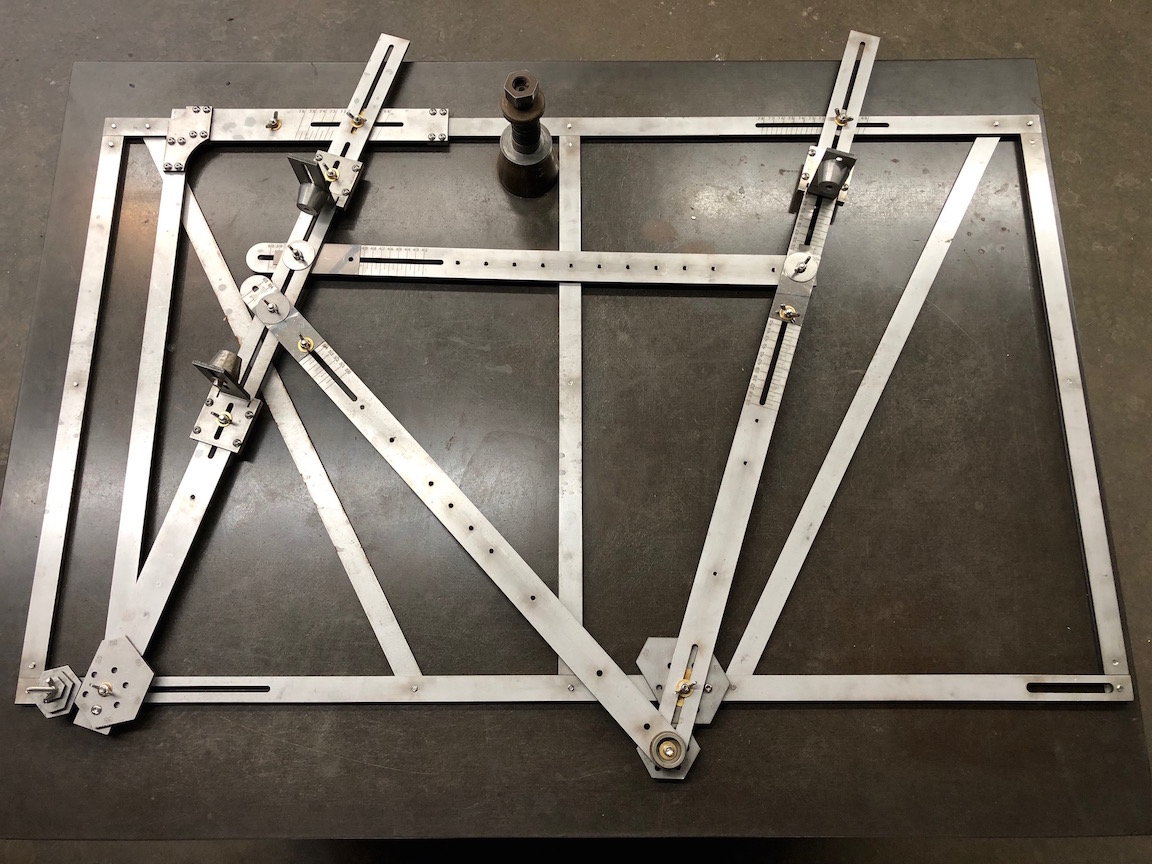
I added a L shaped piece to indicate head tube angle. Hex pieces assist with fork rake and BB drop placement. The seat, top and down tune pieces have markings to show their length to the mm.
The accessories on this model can assist in making to top tube level or slant at a certain amount. The center support markings let me know the straddle height of the top of the top tube. Spinners under the V blocks can adjust their height off of the table. The T shape accessory on the top support shows saddle setback.

This model has accessories for placing a seat and stem in the same position from a fitting bicycle to assist in frame design.

This picture shows the details of positioning saddle setback. Markings show saddle height too. The parallelogram places the bolt on the top horizontal support exactly above the center of the BB.
However I also use my fixture to convert a rider's position that has been found on a fitting bike or by swapping out stems and handlebars on their bike. I never trust body measurements alone. I can place a seat/saddle and stem in the same position on my fixture as it should be on their real bike. There are accessories and markings on the fixture to assist with this placement. Then I move the pieces that represent each tube to match the position of the saddle and stem. Of course during this process, adjustments to stem length might be required.
This process reflects my goals of making riding a bicycle more efficient and comfortable for a recreational cyclist. Many cyclists by middle age can no longer be comfortable in a true racing position. Of course some compromises to what makes the best handling bike have to be made to get a not-slim-not-flexible person into a position that works best for them. The go fastest crowd will be buying a carbon bike anyway. I also find that a lot of my young framebuilding class students prefer a comfortable rather than racing position. They are not using their bikes for fast group training rides.
One thing I like about my fixture is that I can see life size that everything looks proportional. This is especially important for how many stackers or quill extension is above the headset. One other point to consider is where the bottom of the down tube lug is positioned. I can adjust the piece that represents the down tube just so that the down tube slips into the lug perfectly. Lugs very a bit in the distance of the bottom of the lug to the center of the down tube point. Trig doesn't take into consideration this small variable. This isn't a big deal but i like that I don't have to do any math and it is the most accurate method for the lugs being used.
Here is a picture of my most basic model:
I added a L shaped piece to indicate head tube angle. Hex pieces assist with fork rake and BB drop placement. The seat, top and down tune pieces have markings to show their length to the mm.
The accessories on this model can assist in making to top tube level or slant at a certain amount. The center support markings let me know the straddle height of the top of the top tube. Spinners under the V blocks can adjust their height off of the table. The T shape accessory on the top support shows saddle setback.
This model has accessories for placing a seat and stem in the same position from a fitting bicycle to assist in frame design.
This picture shows the details of positioning saddle setback. Markings show saddle height too. The parallelogram places the bolt on the top horizontal support exactly above the center of the BB.
01-12-23, 04:04 PM
#20
framebuilder
My philosophy is that it is better to braze a frame outside of a fixture for several reasons. First, it allows the frame tubes to freely expand and move as it is being heated. Second, it is easiest to move the frame so it is always in the best position throughout the entire brazing sequence when brazing one joint. A fixture restricts movement or gets in the way of your best flame pattern. And finally, it is easier to see what you are doing - this is especially important when brazing tubes to the BB shell so you can see inside.
An adjustable T tool is useful for an amateur builder making lugged frames. It is a time tested and easy enough to make with hand tools. When I was visiting framebuilders in the UK in the 70’s, nearly all of them used one to braze the chainstays/rear dropouts units to the bottom bracket shell. It holds them to the chain stay/seat tube angle that is determined by the bottom bracket drop, seat angle and chainstay length. The rear axle in the T tool holds the dropouts at the chosen width. Some kind of straight edge with an adjustable screw positions the dropouts equidistant from the frame’s centerline (like the Park Frame Alignment Gage). I set my T tool to the right length by placing the frame on my fixture and adjusting its length until the bolt holding the dropout lines up with the rear wheel base slot. One of the advantages of using a T tool while brazing the chainstays into the BB shell is because it is easy to see if the brazing material has reached the end of each shell’s socket. It also avoids frame fixture holding attachments from robbing flame heat at the BB.And allows the frame to be best positioned to braze those joints (because you are only moving the frame and not frame and fixture). Here are some pictures.

The T tool in use

The parts of the T tool

I made a extra long straight length fork as a holding fixture for brazing the T junction
An adjustable T tool is useful for an amateur builder making lugged frames. It is a time tested and easy enough to make with hand tools. When I was visiting framebuilders in the UK in the 70’s, nearly all of them used one to braze the chainstays/rear dropouts units to the bottom bracket shell. It holds them to the chain stay/seat tube angle that is determined by the bottom bracket drop, seat angle and chainstay length. The rear axle in the T tool holds the dropouts at the chosen width. Some kind of straight edge with an adjustable screw positions the dropouts equidistant from the frame’s centerline (like the Park Frame Alignment Gage). I set my T tool to the right length by placing the frame on my fixture and adjusting its length until the bolt holding the dropout lines up with the rear wheel base slot. One of the advantages of using a T tool while brazing the chainstays into the BB shell is because it is easy to see if the brazing material has reached the end of each shell’s socket. It also avoids frame fixture holding attachments from robbing flame heat at the BB.And allows the frame to be best positioned to braze those joints (because you are only moving the frame and not frame and fixture). Here are some pictures.
The T tool in use
The parts of the T tool
I made a extra long straight length fork as a holding fixture for brazing the T junction


