


Internal wiring for dynamo lights: the heads tube connection
 10-26-18, 06:09 AM
#1

multimodal commuter
Thread Starter

Join Date: Nov 2006
Location: NJ, NYC, LI
Posts: 19,808
Bikes: 1940s Fothergill, 1959 Allegro Special, 1963? Claud Butler Olympic Sprint, Lambert 'Clubman', 1974 Fuji "the Ace", 1976 Holdsworth 650b conversion rando bike, 1983 Trek 720 tourer, 1984 Counterpoint Opus II, 1993 Basso Gap, 2010 Downtube 8h, and...
Mentioned: 584 Post(s)
Tagged: 0 Thread(s)
Quoted: 1908 Post(s)
Liked 574 Times
in
339 Posts
Internal wiring for dynamo lights: the heads tube connection
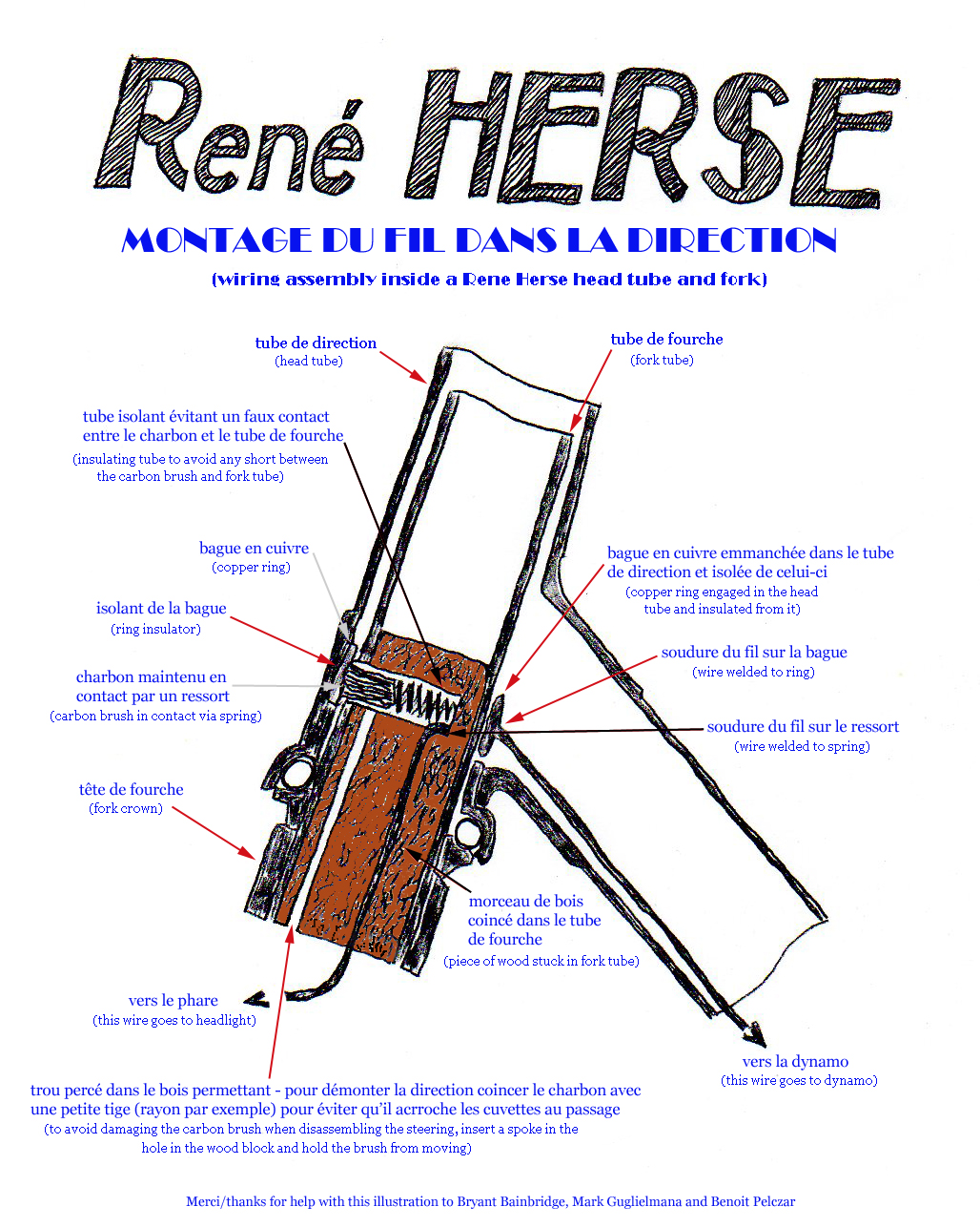
Rene Herse and others used to set up dynamo lights with a wire inside the down tube with a carbon brush connection inside the fork steerer tube. Here's a diagram I found with a little help from Google.
More discussion here:
Ren� Herse randonneuse bicycle
Of course today one would use a dynamo in the front wheel, rather than one running on the rear wheel; otherwise the Herse design should work fine. Has anyone on this forum tried this, or something similar? (calling @gugie, who helped with that illustration). Do you have any experience to share? Suggestions on materials, what kind of carbon brush to use, etc?
__________________
www.rhmsaddles.com.
www.rhmsaddles.com.
Last edited by rhm; 10-26-18 at 06:14 AM.
 10-26-18, 06:12 AM
#2
multimodal commuter
Thread Starter
Join Date: Nov 2006
Location: NJ, NYC, LI
Posts: 19,808
Bikes: 1940s Fothergill, 1959 Allegro Special, 1963? Claud Butler Olympic Sprint, Lambert 'Clubman', 1974 Fuji "the Ace", 1976 Holdsworth 650b conversion rando bike, 1983 Trek 720 tourer, 1984 Counterpoint Opus II, 1993 Basso Gap, 2010 Downtube 8h, and...
Mentioned: 584 Post(s)
Tagged: 0 Thread(s)
Quoted: 1908 Post(s)
Liked 574 Times
in
339 Posts
Attention moderator: Oops, I can't believe I missed that... but can someone please correct the typos in the thread title? It should read "the head tube connection." Thanks!
__________________
www.rhmsaddles.com.
www.rhmsaddles.com.
10-26-18, 07:52 AM
#3

Bike Butcher of Portland

Join Date: Jul 2014
Location: Portland, OR
Posts: 11,630
Bikes: It's complicated.
Mentioned: 1299 Post(s)
Tagged: 0 Thread(s)
Quoted: 4677 Post(s)
Liked 5,790 Times
in
2,279 Posts
Rene Herse and others used to set up dynamo lights with a wire inside the down tube with a carbon brush connection inside the fork steerer tube. Here's a diagram I found with a little help from Google.
More discussion here:
Ren� Herse randonneuse bicycle
Of course today one would use a dynamo in the front wheel, rather than one running on the rear wheel; otherwise the Herse design should work fine. Has anyone on this forum tried this, or something similar? (calling @gugie, who helped with that illustration). Do you have any experience to share? Suggestions on materials, what kind of carbon brush to use, etc?
More discussion here:
Ren� Herse randonneuse bicycle
Of course today one would use a dynamo in the front wheel, rather than one running on the rear wheel; otherwise the Herse design should work fine. Has anyone on this forum tried this, or something similar? (calling @gugie, who helped with that illustration). Do you have any experience to share? Suggestions on materials, what kind of carbon brush to use, etc?
Corey takes a blind water bottle boss, and uses his lathe to remove the threads and drill a small hole on one end. Here's a pic of the boss before machining:
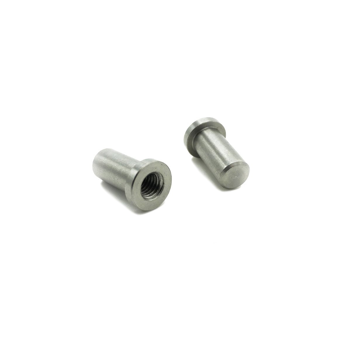
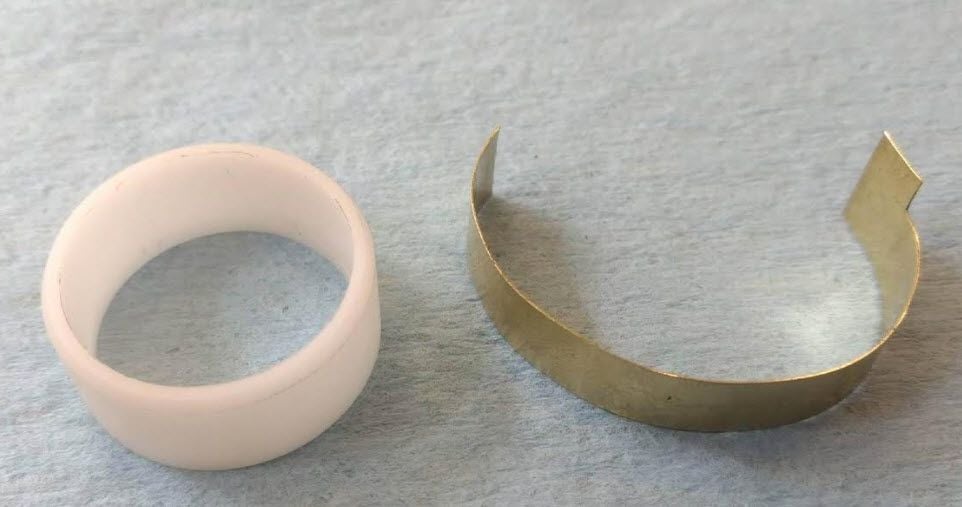
He makes his own brush out of brass and a spring, encases it with heat shrink insulation, and slides that into the boss. The contact ring is thin brass sitting in a machined plastic piece. This goes right above the headset bottom cup. A wire is soldered to the thing brass ring and heads down the downtube.*
I have a more detailed version of all this from Corey, I'll see if he doesn't mind republishing his email and pictures that he sent me. There's a good chance I'll go up to Tacoma sometime near Thanksgiving for a shop visit - he's 6 miles from the Tacoma train station, so I could do a train-bike thing.*
The few people I know who have done this don't use carbon for the brush. The concern is that it will break easily.*
*
__________________
If someone tells you that you have enough bicycles and you don't need any more, stop talking to them. You don't need that kind of negativity in your life.
If someone tells you that you have enough bicycles and you don't need any more, stop talking to them. You don't need that kind of negativity in your life.
10-26-18, 08:14 AM
#4
multimodal commuter
Thread Starter
Join Date: Nov 2006
Location: NJ, NYC, LI
Posts: 19,808
Bikes: 1940s Fothergill, 1959 Allegro Special, 1963? Claud Butler Olympic Sprint, Lambert 'Clubman', 1974 Fuji "the Ace", 1976 Holdsworth 650b conversion rando bike, 1983 Trek 720 tourer, 1984 Counterpoint Opus II, 1993 Basso Gap, 2010 Downtube 8h, and...
Mentioned: 584 Post(s)
Tagged: 0 Thread(s)
Quoted: 1908 Post(s)
Liked 574 Times
in
339 Posts
So the contact is brass against brass? I assume that means more friction, and more wear, but all within an acceptable range?
__________________
www.rhmsaddles.com.
www.rhmsaddles.com.
10-26-18, 08:25 AM
#5


Randomhead
Join Date: Aug 2008
Location: Happy Valley, Pennsylvania
Posts: 24,387
Mentioned: 0 Post(s)
Tagged: 0 Thread(s)
Quoted: 4 Post(s)
Liked 3,687 Times
in
2,510 Posts
I'm making a practice frame with every stupid idea* I can throw at it, so I'm going to do this slip ring nonsense. I'm really too short for a seat tube mounted light to be a good idea, so I might skip that bad idea. So I'm not sure where I'm going to run the tail light wire, probably have it exit at the bb shell.
*also good ideas I have no experience with
brass against copper would be better, same-same material has higher friction and fretting for some reason I only vaguely understand. But that issue ruled my life for a while at a previous job. I just asked John Clay for some clarification on his technique yesterday. https://groups.google.com/forum/#!to...rs/Q9DxcVCtYgs
https://groups.google.com/group/fram...0.1&authuser=0
There is a Hirose video where he sets a frame up like this, but nobody seems to know the link and he has dozens of videos. So looking for that exact video is a real time sink. Hirose winds copper magnet wire into a bed of epoxy and then turns down the OD of the wire. Magnet wire has insulation, and the epoxy should keep it in place where it is needed. I'm thinking of using that technique because John's method of making a ring, stretching it, and then gluing it onto the head tube seems a little too fiddly for me.
For retrofit purposes, external routing at the crown and drilling into the head lug is a lot more practical. I suppose it depends on the size of your vent hole, but there is very little clearance available inside the head tube of a bike with a 1" steerer.
I also haven't quite figured out the routing at the crown. Some tail lights can be powered from a dynohub, but some can't. Turns out that all the fender mounted taillights I have cannot tolerate full dyno voltage and should be powered through the headlight. And I am using dropouts with contacts in them, so the wiring would go up inside the fork blade, exit at the lower rack mount, traverse the rack up to the headlight, then go back to the crown to the slip ring contact.
Last edited by unterhausen; 10-26-18 at 08:41 AM.
10-26-18, 08:56 AM
#6
Randomhead
Join Date: Aug 2008
Location: Happy Valley, Pennsylvania
Posts: 24,387
Mentioned: 0 Post(s)
Tagged: 0 Thread(s)
Quoted: 4 Post(s)
Liked 3,687 Times
in
2,510 Posts
I may just put the brush holder in place and punt on the insulator and brush for now. I feel like I can make the holder a little smaller than John's. Cory's water bottle boss seems awfully small, but I don't know what he does with it.
John's routing where he just takes the taillight wire back to where the dyno hub wire comes in is interesting. have to think about that. I probably would run the wire through the crown though, and I'm thinking about running some small tubing through for ease of wire replacement should that become an issue.
John's routing where he just takes the taillight wire back to where the dyno hub wire comes in is interesting. have to think about that. I probably would run the wire through the crown though, and I'm thinking about running some small tubing through for ease of wire replacement should that become an issue.
10-26-18, 02:54 PM
#7
Bike Butcher of Portland
Join Date: Jul 2014
Location: Portland, OR
Posts: 11,630
Bikes: It's complicated.
Mentioned: 1299 Post(s)
Tagged: 0 Thread(s)
Quoted: 4677 Post(s)
Liked 5,790 Times
in
2,279 Posts
Some pix from Corey:


__________________
If someone tells you that you have enough bicycles and you don't need any more, stop talking to them. You don't need that kind of negativity in your life.
If someone tells you that you have enough bicycles and you don't need any more, stop talking to them. You don't need that kind of negativity in your life.
10-26-18, 03:11 PM
#8
multimodal commuter
Thread Starter
Join Date: Nov 2006
Location: NJ, NYC, LI
Posts: 19,808
Bikes: 1940s Fothergill, 1959 Allegro Special, 1963? Claud Butler Olympic Sprint, Lambert 'Clubman', 1974 Fuji "the Ace", 1976 Holdsworth 650b conversion rando bike, 1983 Trek 720 tourer, 1984 Counterpoint Opus II, 1993 Basso Gap, 2010 Downtube 8h, and...
Mentioned: 584 Post(s)
Tagged: 0 Thread(s)
Quoted: 1908 Post(s)
Liked 574 Times
in
339 Posts
Well since I don't build frames, my project will be retrofitting an old steel racing frame. The bike has a cluster brake mounted on the fork crown, so putting a 7/8� dowel in there to hold the bridg assembly, whether it's copper or carbon, should be easy enough; the brake mounting bolt will hold it in place.
How large a hole can I drill through the steerer without weakening it?
How large a hole can I drill through the steerer without weakening it?
10-26-18, 03:52 PM
#9
Randomhead
Join Date: Aug 2008
Location: Happy Valley, Pennsylvania
Posts: 24,387
Mentioned: 0 Post(s)
Tagged: 0 Thread(s)
Quoted: 4 Post(s)
Liked 3,687 Times
in
2,510 Posts
I wasn't really thinking about the Herse method when I said that retrofit would be difficult, I can see how to make it work no problem.
I'm an engineer, so answering the question about the hole without a full analysis would be malpractice. But my evil twin says about 3/16" on the side of the steerer should be okay. Hole quality is paramount: smooth bore, good transitions from the od/id.
eta: It seems the Herse put the hole in the front. That would normally put it under compression. But I'm pretty sure that braking forces put the front under tension, so that concerns me a little. Seems like the side would be the best worse case.
Last edited by unterhausen; 10-26-18 at 04:01 PM.
10-26-18, 03:59 PM
#10
Randomhead
Join Date: Aug 2008
Location: Happy Valley, Pennsylvania
Posts: 24,387
Mentioned: 0 Post(s)
Tagged: 0 Thread(s)
Quoted: 4 Post(s)
Liked 3,687 Times
in
2,510 Posts
hard to tell, is that the steerer in the first pic? Is the bottle boss brazed inside?
His contact is interesting. Heat shrink tubing has the advantage that I don't have to order an 8 foot long piece of hpde plastic to use as an insulator. Have to think about that.
His contact is interesting. Heat shrink tubing has the advantage that I don't have to order an 8 foot long piece of hpde plastic to use as an insulator. Have to think about that.
Last edited by unterhausen; 10-26-18 at 04:04 PM.
10-26-18, 04:17 PM
#11
Banned
Boulder bikes has Francophile Replicas .
at the if you have to ask you cant afford it prices
general theme 2 electric motor brushes contact 1 ring for + , another for -,
so as to have an on/off knob on top of the steerer.. generators had significant drag BITD.
now hub dynamos have so little drag why bother. ?
a grommet under the top if the down tube and a coiled up length of wire from the fork steerer
and you can run co ax wire all the way to the BB*, and then to inside the rear mudguard,
or on to the rear end of the chainstay
My mid 80's touring bike was built to use the then popular BB generator whis dis have drag
it used that wiring route to the headlight, a halogen bulb at that time..
...
Last edited by fietsbob; 10-26-18 at 04:21 PM.
10-26-18, 05:40 PM
#12
Senior Member

Join Date: Feb 2008
Location: Peoria, IL
Posts: 4,469
Mentioned: 86 Post(s)
Tagged: 0 Thread(s)
Quoted: 1827 Post(s)
Liked 3,367 Times
in
1,573 Posts
.......... @Jmclay has done the inverse - his brush is brazed into the down tube, the contact ring on the fork.*
Still, as an electrical engineer who's been making his own dynamo headlights since before there were white LEDs, I have pondered the various methods and technologies.
John Clay had a thread on the Classic Rendezvous list when he was working on his design. His Flickr album is a nice summary of the work, but he was nice enough to write up a proper report. I stashed away a copy for my own records, and have tossed it up on my google drive so that I can share it with others:
https://drive.google.com/open?id=1Eg...kHSe4UyjSp2_Ee
I'm not sure what the relative merits are between locating the brush in the down tube vs. the steerer tube. Locating the brush in the steerer would seem to require a significantly larger hole in the steerer. Locating the brush in the down tube seems to require installation when the frame is built, as John Clay did. It would require an unusually large vent hole in the head tube to retrofit a brush into the down tube.
As an engineer, it bothered me that no one has come up with a higher tech means to couple the energy across the barrier between the steerer tube and the frame. It bothers me more to admit that I haven't come up with a good way of doing it either.

Steve in Peoria
10-26-18, 05:41 PM
#13
Randomhead
Join Date: Aug 2008
Location: Happy Valley, Pennsylvania
Posts: 24,387
Mentioned: 0 Post(s)
Tagged: 0 Thread(s)
Quoted: 4 Post(s)
Liked 3,687 Times
in
2,510 Posts
The real danger in watching Hirose videos for some of us is that we will end up doing something stupid like make derailleurs or chain rings/crank spiders. He makes all sorts of amazing things.
10-26-18, 05:56 PM
#14
Bike Butcher of Portland
Join Date: Jul 2014
Location: Portland, OR
Posts: 11,630
Bikes: It's complicated.
Mentioned: 1299 Post(s)
Tagged: 0 Thread(s)
Quoted: 4677 Post(s)
Liked 5,790 Times
in
2,279 Posts
this subject really intrigues me... more as a spectator than as a potential participant.
Still, as an electrical engineer who's been making his own dynamo headlights since before there were white LEDs, I have pondered the various methods and technologies.
John Clay had a thread on the Classic Rendezvous list when he was working on his design. His Flickr album is a nice summary of the work, but he was nice enough to write up a proper report. I stashed away a copy for my own records, and have tossed it up on my google drive so that I can share it with others:
https://drive.google.com/open?id=1Eg...kHSe4UyjSp2_Ee
I'm not sure what the relative merits are between locating the brush in the down tube vs. the steerer tube. Locating the brush in the steerer would seem to require a significantly larger hole in the steerer. Locating the brush in the down tube seems to require installation when the frame is built, as John Clay did. It would require an unusually large vent hole in the head tube to retrofit a brush into the down tube.
As an engineer, it bothered me that no one has come up with a higher tech means to couple the energy across the barrier between the steerer tube and the frame. It bothers me more to admit that I haven't come up with a good way of doing it either.
Steve in Peoria
I'm with you, I'm bothered that you haven't come up with a good way to do it.
;-)
__________________
If someone tells you that you have enough bicycles and you don't need any more, stop talking to them. You don't need that kind of negativity in your life.
If someone tells you that you have enough bicycles and you don't need any more, stop talking to them. You don't need that kind of negativity in your life.
10-26-18, 06:54 PM
#15
Randomhead
Join Date: Aug 2008
Location: Happy Valley, Pennsylvania
Posts: 24,387
Mentioned: 0 Post(s)
Tagged: 0 Thread(s)
Quoted: 4 Post(s)
Liked 3,687 Times
in
2,510 Posts
slip rings are still very common in signal transmission, although growing less common now due to wireless. But for power, I don't see slip rings going away any time soon. My hesitation with the slip ring idea is that I'm worried about reliability. Don't want to find out my tail light isn't working. No way I'm going to an inductive coupling scheme, which seems to be the current wireless power transmission scheme of choice.
I think this can be done with a normal size vent hole if you use the Hirose/Clay method.
I think this can be done with a normal size vent hole if you use the Hirose/Clay method.
10-26-18, 08:06 PM
#16
Senior Member
Join Date: May 2013
Posts: 80
Mentioned: 4 Post(s)
Tagged: 0 Thread(s)
Quoted: 21 Post(s)
Likes: 0
Liked 16 Times
in
8 Posts
I just saw this conversation. A couple of comments.
Crown Race Installation: The offset solder tab allows the race to clear the solder joint before the race has to accommodate the entire circumference.
I chose the Hirose method because the hole in the steerer could be much smaller. It also seemed easier to fabricate.
Brass brush on copper ring to reduce galling.
Making the ring is a bit fiddly but not really that difficult. I much like that the seam is soldered and smoothed so that full rotations are no problem.
The brush capsule could be of smaller diameter.
I forgot to drill the hole that was required for internal routing from fork leg into crown socket and into steerer ID so it pops out immediately under the crown and then enters the steerer; I didn't forget that on the current RTP frame I'm building!
I haven't ridden much at night but I check operation whenever I ride and ask my friends to let me know if the taillight isn't running continuously; no problems so far.
10-27-18, 06:40 AM
#17
Cycleway town

Why not just put the dynamo on the rear wheel?
10-27-18, 07:45 AM
#18
Randomhead
Join Date: Aug 2008
Location: Happy Valley, Pennsylvania
Posts: 24,387
Mentioned: 0 Post(s)
Tagged: 0 Thread(s)
Quoted: 4 Post(s)
Liked 3,687 Times
in
2,510 Posts
10-27-18, 01:19 PM
#19
Cycleway town
Hmm. Mount your headlight on the side of your top tube, next to the head tube.
You can pass a cable through the head tube, so from the badge to the top/down tubes, if you wanted to mount the lamp on the head tube. There's enough room in the void between the inner wall of the head tube and the outer wall of the steerer. You'd still have unlimited 360 degree steering turns.
In fact, this way you could pass a cable from the centre of the steerer tube into that void without breaking it when steering; pass it through at different heights and loosely wrap it around the steerer several times so it's like a coil spring. This would mean your steering would be limited to the amount of 360 degree turns, though.
10-27-18, 02:01 PM
#20
Banned
somewhere I saw a freehub with a dynamo in it , maybe for tad pole trikes..
Extra wheel bike trailers use a 2nd front wheel
so if you have a lot of electronics with you on tour , with you
they get a separate hub dynamo..
....
Extra wheel bike trailers use a 2nd front wheel
so if you have a lot of electronics with you on tour , with you
they get a separate hub dynamo..
....
10-27-18, 04:28 PM
#21
Randomhead
Join Date: Aug 2008
Location: Happy Valley, Pennsylvania
Posts: 24,387
Mentioned: 0 Post(s)
Tagged: 0 Thread(s)
Quoted: 4 Post(s)
Liked 3,687 Times
in
2,510 Posts
In case you couldn't tell, this is discussion about a specific style of wiring that involves a slip ring in the head tube, and we aren't really looking for alternatives to that.
10-27-18, 06:00 PM
#22
Senior Member
Join Date: May 2013
Posts: 80
Mentioned: 4 Post(s)
Tagged: 0 Thread(s)
Quoted: 21 Post(s)
Likes: 0
Liked 16 Times
in
8 Posts
this subject really intrigues me... more as a spectator than as a potential participant.
Still, as an electrical engineer who's been making his own dynamo headlights since before there were white LEDs, I have pondered the various methods and technologies.
John Clay had a thread on the Classic Rendezvous list when he was working on his design. His Flickr album is a nice summary of the work, but he was nice enough to write up a proper report. I stashed away a copy for my own records, and have tossed it up on my google drive so that I can share it with others:
https://drive.google.com/open?id=1Eg...kHSe4UyjSp2_Ee
I'm not sure what the relative merits are between locating the brush in the down tube vs. the steerer tube. Locating the brush in the steerer would seem to require a significantly larger hole in the steerer. Locating the brush in the down tube seems to require installation when the frame is built, as John Clay did. It would require an unusually large vent hole in the head tube to retrofit a brush into the down tube.
As an engineer, it bothered me that no one has come up with a higher tech means to couple the energy across the barrier between the steerer tube and the frame. It bothers me more to admit that I haven't come up with a good way of doing it either.
Steve in Peoria
Still, as an electrical engineer who's been making his own dynamo headlights since before there were white LEDs, I have pondered the various methods and technologies.
John Clay had a thread on the Classic Rendezvous list when he was working on his design. His Flickr album is a nice summary of the work, but he was nice enough to write up a proper report. I stashed away a copy for my own records, and have tossed it up on my google drive so that I can share it with others:
https://drive.google.com/open?id=1Eg...kHSe4UyjSp2_Ee
I'm not sure what the relative merits are between locating the brush in the down tube vs. the steerer tube. Locating the brush in the steerer would seem to require a significantly larger hole in the steerer. Locating the brush in the down tube seems to require installation when the frame is built, as John Clay did. It would require an unusually large vent hole in the head tube to retrofit a brush into the down tube.
As an engineer, it bothered me that no one has come up with a higher tech means to couple the energy across the barrier between the steerer tube and the frame. It bothers me more to admit that I haven't come up with a good way of doing it either.
Steve in Peoria
10-27-18, 06:26 PM
#23
Senior Member
Join Date: Feb 2008
Location: Peoria, IL
Posts: 4,469
Mentioned: 86 Post(s)
Tagged: 0 Thread(s)
Quoted: 1827 Post(s)
Liked 3,367 Times
in
1,573 Posts
Thanks Steve! My hope was that by laying my (admittedly lengthy) thought process and course of action out, it would help others and speed all of us towards improvements figured out by others. I'm happy to answer questions or further explain how I went about this exercise, on the list.
Considering the speed of the armatures, the brushes must have traveled quite a long distance over the contacts on the armature (what are those contacts called?). Seems like it would be a much more demanding application than steerer tube brush, but how often do they wear out? I can't remember having one fail.
I will admit that most of these brushes would likely be too large to mount in a steerer tube, if only due to the large hole that would need to be created in the tube. A lot of these brush assemblies were pretty long too, so possibly difficult to insert into the down tube??
The odds of me ever trying to fabricate any of this stuff is incredibly small, but I can't help but ponder the technical aspects of other ways of getting the power transferred using other means. Everything seems to have pretty severe shortcomings. I ran some numbers on how to use differential capacitance to couple the power, but the available capacitance is so small that it would have to be driven with an AC waveform that was into the gigahertz range. Definitely not practical!
Using magnetic fields didn't seem practical either, especially with so much steel nearby to divert the magnetic field. I've got one idea that has a slim chance of working... not that it would be easy to prototype, though.
I've considered the idea of using light pipes and fiber optics to just send light across the barrier instead of electrons. I've got very little experience in this area, despite having taken a class on optical waveguides in semiconductor devices (needed it to finish my masters), but can foresee difficulties. Also, it's not especially friendly towards the hobbyist.
Anyway, it's one of those subjects that is pretty much wide open for tinkering and experimentation! Love it!
Steve in Peoria
10-27-18, 08:25 PM
#24
Senior Member
Join Date: May 2013
Posts: 80
Mentioned: 4 Post(s)
Tagged: 0 Thread(s)
Quoted: 21 Post(s)
Likes: 0
Liked 16 Times
in
8 Posts
It's concern about breaking carbon brushes while inserting and removing the fork. Electrically there is no doubt they'd be superior.
The commercial carbon brush unit that I modified for prototyping was so overhung that it would have been easy to break; or difficult not to! I considered drilling the center of the brass brush and soldering a round carbon brush in the cavity. Haven't done that but might give it a try on a test piece sometime.
The commercial carbon brush unit that I modified for prototyping was so overhung that it would have been easy to break; or difficult not to! I considered drilling the center of the brass brush and soldering a round carbon brush in the cavity. Haven't done that but might give it a try on a test piece sometime.
Last edited by Jmclay; 10-28-18 at 05:51 AM.
10-27-18, 09:35 PM
#25
multimodal commuter
Thread Starter
Join Date: Nov 2006
Location: NJ, NYC, LI
Posts: 19,808
Bikes: 1940s Fothergill, 1959 Allegro Special, 1963? Claud Butler Olympic Sprint, Lambert 'Clubman', 1974 Fuji "the Ace", 1976 Holdsworth 650b conversion rando bike, 1983 Trek 720 tourer, 1984 Counterpoint Opus II, 1993 Basso Gap, 2010 Downtube 8h, and...
Mentioned: 584 Post(s)
Tagged: 0 Thread(s)
Quoted: 1908 Post(s)
Liked 574 Times
in
339 Posts
Well, I futzed around with this for several hours today, learned a lot, most of it negative (don't do it this way... and don't do it that way...) and eventually ended up with a tail light that I thought was good to go. But when I plugged it in to the head light, it wouldn't. The headlight works until I plug the tail light in to it, then nothing works.
Obviously there is a short circuit somewhere, but I haven't had a chance to diagnose it. I suspect it's in the tail light itself, but I suppose it could be anywhere.
Shimano did make rear dynamo hubs for a short while a few years ago. They were low power, but probably good for powering a tail light.