


DIY carbon seatpost
 11-16-21, 02:48 PM
#1
Junior Member
Thread Starter
DIY carbon seatpost
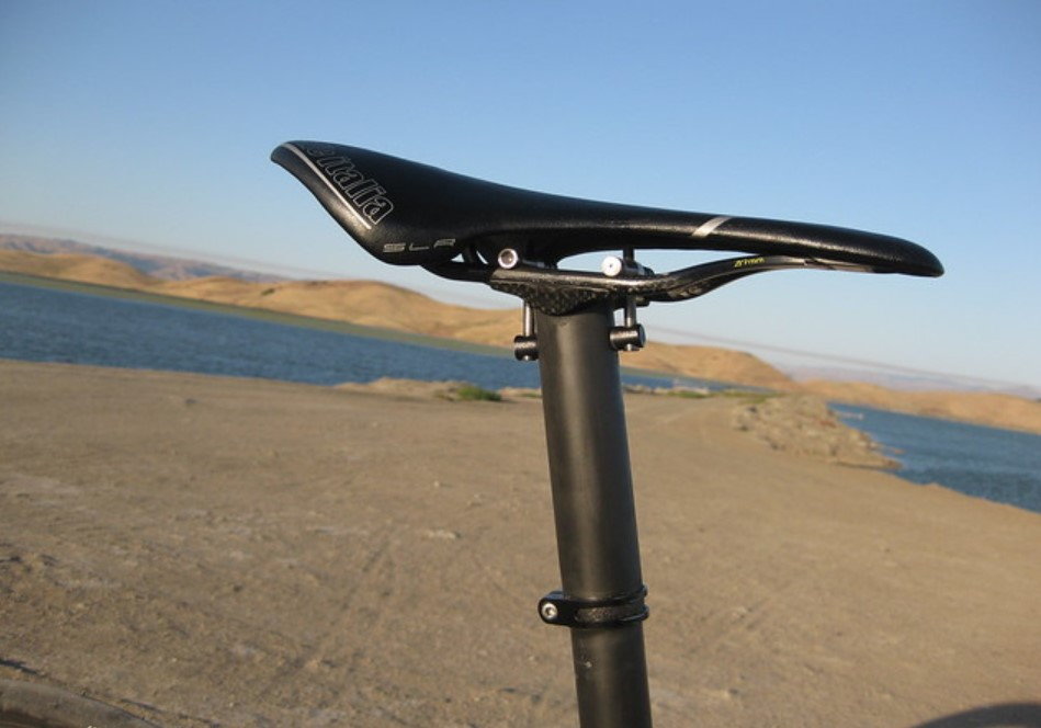
Hi all. I'm after a zero-setback carbon seatpost for my Look KG96 (with which I'm utterly in love) and its 25.0 mm seat tube ID. Alu models I've found are either too stiff and have setback (the ErgoTec post I have at the moment) or too stiff and expensive (the Thomson Elite). Look's own carbon ErgoPosts are badly made, expensive, and aren't long enough for my needs. WR Composti made 25 mm carbon seatposts, but they are (or were) very expensive and with setback.
So my idea is to make my own, hopefully using a 27.2 mm KCNC scandium I have and a carbon tube. A couple of ideas:
1) Use the bits from the KCNC head and cut the end of the carbon tube to fit as well as drilling holes for the cross piece (something close to this: https://www.schmolke-carbon.com/_ben6009/).
2) Cut a short section off the top of the KCNC post and bond the carbon tube inside it with epoxy. The ID of the KCNC should be about 25.4 mm, giving 0.2 mm of space for the epoxy, which is just right. I'd roughen the surface up, clean them with acetone, and use glass beads to maintain the spacing while the epoxy cures.
3) Find a seatpost head with a 22-23mm ID to insert into the carbon tube.
4) Something like the Ritchey Mast Topper.
I assume (1) will require some pretty careful cutting and drilling of the carbon and is possibly too difficult to do safely without special tooling. I can't find something like (3) anywhere. (4) seems like it could work well, but the same problems arise regarding the 25mm diameter (min size for the Ritchey is 30.25mm ID---too much of a disparity to shim). I saw a 27.4mm Ti one on eBay, but at 135 dollars.
Any thoughts about the tools required for (1)? And any refinements to (2) such as optimal bonded section length?
Last edited by Jonneh; 11-16-21 at 04:47 PM. Reason: More detailed questions
 11-16-21, 03:02 PM
#2
Senior Member
Join Date: Jul 2013
Location: Nor-Cal
Posts: 3,767
Bikes: lots
Mentioned: 7 Post(s)
Tagged: 0 Thread(s)
Quoted: 1958 Post(s)
Liked 2,932 Times
in
1,489 Posts

Likes For cxwrench:
11-16-21, 03:35 PM
#3

Mother Nature's Son

Join Date: Mar 2016
Location: Sussex County, Delaware
Posts: 3,107
Bikes: 2014 Orbea Avant MD30, 2004 Airborne Zeppelin TI, 2003 Lemond Poprad, 2001 Lemond Tourmalet, 2014? Soma Smoothie
Mentioned: 15 Post(s)
Tagged: 0 Thread(s)
Quoted: 852 Post(s)
Liked 1,433 Times
in
815 Posts
I have thoughts on the whole thing, NOT ME. Go ahead with it if you are comfortable with it. Report back to the BF with time, cost, quality and safety of the finished product, please.
11-16-21, 03:45 PM
#4
LR�P=HR
Join Date: Sep 2019
Location: SF Bay Area
Posts: 2,161
Bikes: 1981 Holdsworth Special, 1993 C-dale MT3000 & 1996 F700CAD3, 2018 Cervelo R3 & 2022 R5, JustGo Runt, Ridley Oval, Kickr Bike 8-)
Mentioned: 1 Post(s)
Tagged: 0 Thread(s)
Quoted: 862 Post(s)
Liked 1,195 Times
in
687 Posts
DIY Seatpost
I would not attempt this for my bike.
This is a high stress item. A failure in this item would cause unpredictable results.
That said, maybe you do have the engineering and composite construction skills to do this.
If so, I wish you all the best and I'm intrigued.
Barry
This is a high stress item. A failure in this item would cause unpredictable results.
That said, maybe you do have the engineering and composite construction skills to do this.
If so, I wish you all the best and I'm intrigued.
Barry
11-16-21, 05:04 PM
#5
Junior Member
Thread Starter
For better or worse, I am comfortable with it, although whether or not comfort is the best guide to safety, I'm not so sure. In any case, I'd hope to be even more comfortable after a discussion (I know there are lots of tinkerers, mechanics, engineers and co. here).
Remaining doubts include the minimum safe bond section length and whether drilling holes in the carbon tube with a carbide bit that align with the holes in the KCNC tube that are about 10mm from the cup is a net benefit despite possible delamination around the hole or whether it makes sense to start the bonded section below the KCNC's holes.
If anyone knows of any type-(3) or -(4) pieces that I haven't been able to find but would be fit for purpose, that'd be welcome knowledge too!
Finally, perhaps I'm wrong about the difficulty of (1), in which case I'd be interested in hearing what doing it properly would involve.
11-16-21, 05:34 PM
#6
Senior Member
Join Date: Aug 2005
Location: Pittsburgh, PA
Posts: 33,656
Bikes: '96 Litespeed Catalyst, '05 Litespeed Firenze, '06 Litespeed Tuscany, '20 Surly Midnight Special, All are 3x10. It is hilly around here!
Mentioned: 39 Post(s)
Tagged: 0 Thread(s)
Quoted: 2026 Post(s)
Likes: 0
Liked 1,095 Times
in
741 Posts
My recommendation; Pay the money and buy the Thomson. Safer and probably less expensive by the time you are done.
Likes For HillRider:
11-16-21, 05:53 PM
#7
Senior Member
Join Date: Jan 2009
Location: San Diego, CA
Posts: 3,661
Mentioned: 10 Post(s)
Tagged: 0 Thread(s)
Quoted: 836 Post(s)
Liked 1,058 Times
in
742 Posts
Here's a Cannondale 25.4mm Carbon 350mm, new ("taken off floor model"), looks like zero setback-maybe, on Ebay. Cannondale TWO 25.4 x 350 Carbon Seatpost | eBay I believe a few Cannondale's also use the 25.4 size so you might find some more options searching. Another possibility. FSA SL-K carbon post (SB0) 25.4 x 350mm 400310033246 | eBay
Last edited by Crankycrank; 11-16-21 at 06:13 PM.
11-16-21, 06:01 PM
#9
Junior Member
Thread Starter
11-16-21, 08:15 PM
#11
Senior Member
Join Date: Sep 2004
Location: Chicago area
Posts: 2,546
Bikes: Airborne "Carpe Diem", Motobecane "Mirage", Trek 6000, Strida 2, Dahon "Helios XL", Dahon "Mu XL", Tern "Verge S11i"
Mentioned: 22 Post(s)
Tagged: 0 Thread(s)
Quoted: 980 Post(s)
Liked 580 Times
in
398 Posts
 11-16-21, 10:57 PM
#12
Senior Member
Join Date: Apr 2012
Location: Nor Cal
Posts: 6,016
Mentioned: 17 Post(s)
Tagged: 0 Thread(s)
Quoted: 1814 Post(s)
Likes: 0
Liked 923 Times
in
569 Posts
Don't need (or want) a carbide drill bit for holes. A diamond hole saw is nice, but regular drill bit works pretty well.
A good all around tutorial:
drilling shown at 10:30
A good all around tutorial:
drilling shown at 10:30
11-17-21, 08:38 AM
#13
Junior Member
Thread Starter
Brilliant, thanks! This is definitely happening. (1) is looking more doable, is inherently more elegant than (2), and avoids the need for finding a seatpost with a 25.4 mm mm ID to have a perfect slip fit (the KCNC is going to be too narrow in the end).
The next question is whether a 3mm wall thickness for the CF tube will be sufficient on its own to resist the stresses on the holes in (1), or whether I'd be best off bonding a short (perhaps 30 mm) metal sleeve (choice of metal TBD) inside the top few cm of the CF tube to reinforce the holes. I'd bond it in first, dremel/junior saw out the approx. semi-circular section and finish with a rounded permagrit file, and then drill the holes for the cross piece. I suppose I'll need to apply a lacquer around the rim once cut to prevent galvanic corrosion if the insert is aluminium. I've seen styles around with and without the (alu, in the case I saw) insert. I'm tall and weigh close to 200lbs, so I'd be going for a thicker than standard tube thickness anyway.
Any thoughts on whether this will obviate the need for a bonded insert where the holes will be drilled?
Last edited by Jonneh; 11-17-21 at 08:42 AM.
11-17-21, 09:13 AM
#14
Senior Member
Join Date: Feb 2012
Location: Rochester, NY
Posts: 18,056
Bikes: Stewart S&S coupled sport tourer, Stewart Sunday light, Stewart Commuting, Stewart Touring, Co Motion Tandem, Stewart 3-Spd, Stewart Track, Fuji Finest, Mongoose Tomac ATB, GT Bravado ATB, JCP Folder, Stewart 650B ATB
Mentioned: 0 Post(s)
Tagged: 0 Thread(s)
Quoted: 4195 Post(s)
Liked 3,837 Times
in
2,295 Posts
Has the compressive strength of the carbon tube been looked at? Has the tube been test fitted into the frame, tightened then stressed a bit? Not just in a bending manor but also in a twisting one (and this will help test the ability for the tube to stay put, better to find out now). The reason I bring this aspect up is that I question whether the tube was designed to resist the compressive forces a seat clap can produce.
The strength of the bonding agent needs to be known as well as the level of stress that the post/top clamp joint will see. The surface contact area needs to be at least enough to result in a joint that is stronger then the tube.
Most bonding agents (epoxy) has an ideal fit up gap that it's specs are based on. I seriously doubt this is as much as 2mm gap. (Most likely the gap is more like tenths of a mm). For someone with a lathe and the skill to use it it shouldn't be hard to both bore the clamp's ID and to turn out a shim to fill any gap, have the gap/fit be consistent along it's length and end up with that ideal fit up gap.
I question whether a pin or bolt running across and through the joint is needed at all. Pins are generally needed for rotational alignment or to increase the amount of torque the joint can handle. I don't think the clamp/post joint needs a large rotational strength and poorly done/located holes and through pin fit up might only weaken the joint (or produce stress focusing points)
I had started a reply yesterday but decided then that my contribution wasn't going to be significant so I moved on. That draft ended with what Dave said. Get the Thompson and go for a ride sooner. Andy
__________________
AndrewRStewart
AndrewRStewart
11-17-21, 09:22 AM
#15
LR�P=HR
Join Date: Sep 2019
Location: SF Bay Area
Posts: 2,161
Bikes: 1981 Holdsworth Special, 1993 C-dale MT3000 & 1996 F700CAD3, 2018 Cervelo R3 & 2022 R5, JustGo Runt, Ridley Oval, Kickr Bike 8-)
Mentioned: 1 Post(s)
Tagged: 0 Thread(s)
Quoted: 862 Post(s)
Liked 1,195 Times
in
687 Posts
You when you see a GIF of a guy on a skateboard approaching a wall, and you have to look away��
unsubscribed

unsubscribed
11-17-21, 09:30 AM
#16
Senior Member
Join Date: Jun 2018
Location: SW Ohio
Posts: 2,397
Mentioned: 93 Post(s)
Tagged: 0 Thread(s)
Quoted: 1104 Post(s)
Liked 1,824 Times
in
878 Posts
There's no way in the world I'd ride on ANYTHING I made. That said, just because I don't have the brains and skill to do it, doesn't mean the OP can't get it done. I'm in to see how this one turns out and I don't just mean the seat post fabrication.
__________________
11-17-21, 09:53 AM
#17
Junior Member
Thread Starter
Thanks for the great details Andrew---these are exactly the kinds of things that I was hoping to discuss. I don't have the carbon tube yet, so these are characteristics I'll have to select for when buying. I'll be sure to put a length of it that I won't be using through the various tests you describe.
You're right about the clearance between the two tubes---I revised this soon after my OP. I would aim for a clearance of 0.2mm. Hopefully this can be nailed when buying the tubes, but I know a machinist or two if that fails.
The pin that you describe doesn't serve any structural role in the union of the alu insert and carbon tube; it is simply part of the clamping mechanism that I'd be stealing from the KCNC post. It's something very similar to this: https://www.schmolke-carbon.com/_ben6009/. The pin is the cross piece that the bolts to the clamp pass through.
All of the above may be moot if an insert isn't needed because the carbon tubes are apt to withstand the forces the cross piece will exert on it. Beyond empirical testing, I don't have the chops to calculate this. Even if the insert is required, it doesn't seem to me like the bond itself will be bearing much of the load. Imagine a 30mm alu section inside the top part of the linked picture. I would cut it to have the same external shape as the carbon so as to receive the arced cup and then drill the holes through the two layers. The cross piece will exert equal force on the two layers, and these will be borne by the cup that the layers butt against. The role of the bonding here would be to ensure that any small differences in the distance between the top of the hole and the arced cup won't mean that all of the load will be borne by either the alu or the carbon. Beyond these shear forces from the clamping mechanism, the continuous bending the the whole section will need to withstand might mean that a somewhat flexible resin would be most appropriate?
Rest assured that I'm riding my bike in the meantime, with a workaround for the setback issue. That's the priority, I agree!
11-17-21, 09:59 AM
#18
Junior Member
Thread Starter
Hehe. I don't promise to be as good an entertainer as the lad who made a broom handle extension for his fork steerer and the inevitable happened (in all seriousness, thank god he was OK). I'll keep you posted though (presuming I can).
Likes For Jonneh:
11-17-21, 10:53 AM
#19

Senior Member

Join Date: Jul 2006
Location: San Jose (Willow Glen) Ca
Posts: 9,834
Bikes: Kirk Custom JK Special, '84 Team Miyata,(dura ace old school) 80?? SR Semi-Pro 600 Arabesque
Mentioned: 106 Post(s)
Tagged: 0 Thread(s)
Quoted: 2337 Post(s)
Liked 2,809 Times
in
1,534 Posts
I understand wanting to build things and the result ending up costing more, I have done that plenty and probably will do it again
I don't understand experimenting for a risky one off without the background to do it with results meeting wants being very unlikely
Consistent response has been: don't do it and that is the best plan
otherwise hope your health insurance is good
I don't understand experimenting for a risky one off without the background to do it with results meeting wants being very unlikely
Consistent response has been: don't do it and that is the best plan
otherwise hope your health insurance is good
__________________
Life is too short not to ride the best bike you have, as much as you can
(looking for Torpado Super light frame/fork or for Raleigh International frame fork 58cm)
Life is too short not to ride the best bike you have, as much as you can
(looking for Torpado Super light frame/fork or for Raleigh International frame fork 58cm)
11-17-21, 11:37 AM
#20
Junior Member
Thread Starter
I understand wanting to build things and the result ending up costing more, I have done that plenty and probably will do it again
I don't understand experimenting for a risky one off without the background to do it with results meeting wants being very unlikely
Consistent response has been: don't do it and that is the best plan
otherwise hope your health insurance is good
I don't understand experimenting for a risky one off without the background to do it with results meeting wants being very unlikely
Consistent response has been: don't do it and that is the best plan
otherwise hope your health insurance is good
I know the precautionary principle is the prevailing bias here, in contrast to other places. Perhaps that's a good thing for many, but failing being trained as an engineer, one only gains the background by doing, and what starts as a one-off may turn into a habit. Aside from what I personally trained in, which is science, that's true for literally everything I know how to do, including projects where my physical safety was at stake. The important thing here is being able to judge that results haven't met wants and not riding the finished product if that is the case. That could be through a mix of measuring tolerances and finish throughout the process and empirical testing on a prototype. These are things I'm willing to do. Before then, I hope to do everything possible to get it right first time.
Unfortunately, "don't do it" or "just buy a ready-made one" loses its impact when it's the default response to almost any kind of DIY proposal. I've seen it many times when the helpful response would have been a technical explanation of the pitfalls, presuming the naysayer actually possesses that knowledge. If it's just intuition, that's OK too, but that should be made clear.
To give a couple of examples from here, I needed a compression plug for a carbon fork. The modal response was that anything DIY was a terrible idea and that I needed to buy the 60 dollar part from Trek. DaveSSS, a mechanical engineer, explained why an epoxy plug would fulfil the required requisites in terms of resisting compression forces. I made it, and it's resisted two years of daily abuse. I also had trouble adapting the same fork to my frame because the integrated race wasn't compatible with any existing bearings. One of the posters, who was actually very helpful, said to just get a new fork. I got in touch with a guy who understood the stresses involved and had machined a shim for the same purpose, installed it, and have been riding happily since.
I don't mean to be rude to anyone---I know intentions are good. It's just that once you've identified what kind of poster you're dealing with, it's sometimes best just to delve into the technical details. That way, everyone learns (including who knows how many lurkers), and the knowledge is applicable to many other things.
Likes For Jonneh:
11-17-21, 04:13 PM
#21
Full Member

Here's a guy who made a zero offset seat mast for Trek
https://weightweenies.starbike.com/f...rt=30#p1145932
https://weightweenies.starbike.com/f...rt=30#p1145932
11-17-21, 04:48 PM
#22
Senior Member

Join Date: Jan 2005
Location: Baltimore, MD
Posts: 5,361
Mentioned: 15 Post(s)
Tagged: 0 Thread(s)
Quoted: 2479 Post(s)
Liked 2,947 Times
in
1,673 Posts
To give a couple of examples from here, I needed a compression plug for a carbon fork. The modal response was that anything DIY was a terrible idea and that I needed to buy the 60 dollar part from Trek. DaveSSS, a mechanical engineer, explained why an epoxy plug would fulfil the required requisites in terms of resisting compression forces. I made it, and it's resisted two years of daily abuse. I also had trouble adapting the same fork to my frame because the integrated race wasn't compatible with any existing bearings. One of the posters, who was actually very helpful, said to just get a new fork. I got in touch with a guy who understood the stresses involved and had machined a shim for the same purpose, installed it, and have been riding happily since.
Same deal for the custom shim. All you had to do was get the dimensions right. And little or no chance of failure if you got them wrong.
11-17-21, 04:55 PM
#23
Senior Member
Join Date: Jan 2005
Location: Baltimore, MD
Posts: 5,361
Mentioned: 15 Post(s)
Tagged: 0 Thread(s)
Quoted: 2479 Post(s)
Liked 2,947 Times
in
1,673 Posts
By the way, Walmart lists a 25.4 carbon seatpost with what looks like nearly zero setback. Out of stock until December 6th, according to the page I looked at. Under $30. It's probably aluminum wrapped in carbon fiber, but then that describes at least half of the "carbon fiber" seatposts on the market. In any event, it can get the bike on the road while you make your plans for constructing the post you really want.
11-17-21, 05:10 PM
#24
Junior Member
Thread Starter
That thing looks great! It's pretty close to what I had in mind, essential being a recreation of the KCNC donor with a carbon tube. Given the list of materials and tools he quotes, he doesn't seem to have bonded any kind of insert inside. I see that the wall thickness of the seatpost tubing Rock West Composites sell is around 2.5 mm, so 3 sounds sensible for me---I'm happy to have it somewhat overbuilt.
11-17-21, 05:19 PM
#25
Junior Member
Thread Starter
Compression plugs see only a small amount of force, since the only requirement is that they allow setting the preload on the headset bearings.
Same deal for the custom shim. All you had to do was get the dimensions right. And little or no chance of failure if you got them wrong.
Same deal for the custom shim. All you had to do was get the dimensions right. And little or no chance of failure if you got them wrong.
In general, I think most points of failure on a bike can be pretty catastrophic (don't ask me how I know). Bars, stem, and fork are especially bad news, but severe tyre blowouts, tubular rolls, chain breakages, and crank and pedal failures can be pretty serious if putting down the power standing up. Honestly, along with certain types of frame failure, a seatpost breakage would probably be among my top picks! I had a clamp bolt fail once, at which point the (too small) seatpost instantly telescoped into the frame, and I was surprised that the reflex fully caught me, my legs taking the load immediately without my going down with the plummeting saddle.
Re the seatpost you mention, the problem has been that I need a 25.0 mm seatpost (Look, Vitus, etc.) and not a 25.4 mm one. Luckily, the bike is in action with the alloy setback post I have, so I can take my time on this current project and do it right.