


Internal wiring for dynamo lights: the heads tube connection
 11-13-18, 11:21 AM
#51

multimodal commuter
Thread Starter

Join Date: Nov 2006
Location: NJ, NYC, LI
Posts: 19,808
Bikes: 1940s Fothergill, 1959 Allegro Special, 1963? Claud Butler Olympic Sprint, Lambert 'Clubman', 1974 Fuji "the Ace", 1976 Holdsworth 650b conversion rando bike, 1983 Trek 720 tourer, 1984 Counterpoint Opus II, 1993 Basso Gap, 2010 Downtube 8h, and...
Mentioned: 584 Post(s)
Tagged: 0 Thread(s)
Quoted: 1908 Post(s)
Liked 574 Times
in
339 Posts
How easy is it to adjust the size of the brushes, with sandpaper or a file or something?
__________________
www.rhmsaddles.com.
www.rhmsaddles.com.
 11-13-18, 11:37 AM
#52


Randomhead
Join Date: Aug 2008
Location: Happy Valley, Pennsylvania
Posts: 24,383
Mentioned: 0 Post(s)
Tagged: 0 Thread(s)
Quoted: 4 Post(s)
Liked 3,684 Times
in
2,508 Posts
it's not too bad. I used an old oilstone, and got it down .02mm before i got bored, which happens fairly quickly. Now my oilstone looks like a 3 y.o. went crazy with a pencil on it.
I'm not sure what an appropriate sliding fit is for these things. I feel like if I design it to 4mm, then it will be rough enough that it will be fine with a smaller brush. And a little acetone should open it up if needed.
I'm not sure what an appropriate sliding fit is for these things. I feel like if I design it to 4mm, then it will be rough enough that it will be fine with a smaller brush. And a little acetone should open it up if needed.
11-13-18, 12:09 PM
#53
Randomhead
Join Date: Aug 2008
Location: Happy Valley, Pennsylvania
Posts: 24,383
Mentioned: 0 Post(s)
Tagged: 0 Thread(s)
Quoted: 4 Post(s)
Liked 3,684 Times
in
2,508 Posts
I can add a lot of these together before they start charging more for the cheapest plastic. Still $5 for 4 of them. I just added them together until I got bored, is there a theme developing here?
I probably would make a join between parts that is easier to separate, but I just wanted to try it. Intention is to experiment with tolerances and hole sizes.
I probably would make a join between parts that is easier to separate, but I just wanted to try it. Intention is to experiment with tolerances and hole sizes.
05-06-19, 08:45 PM
#54
Senior Member
Join Date: May 2013
Posts: 80
Mentioned: 4 Post(s)
Tagged: 0 Thread(s)
Quoted: 21 Post(s)
Likes: 0
Liked 16 Times
in
8 Posts
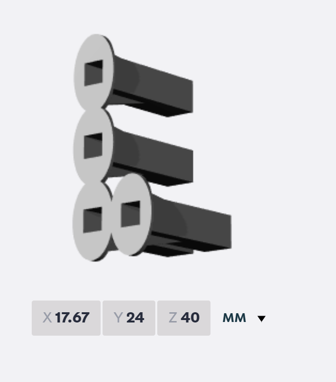
Updates and improvements in making the slip ring, forged as a result of screwing up.
I forgot to make the tab when I cut this slip ring out of my sheet of copper; not wanting to waste it I forged ahead, thinking I might be able to make a thin enough solder joint (in spite of the prototyping lessons to the contrary). So I just soldered the wire directly onto it as shown in this photo: www.flickr.com/photos/21624415@N04/33754623348/in/datepos...
As was the case during the prototyping the lump was too thick. Additionally the insulated B&M wire has a large OD, relative to the clearances we're working with. Inserting the fork damaged the wiring. I decided to try to add a tab offset, in situ, to this ring instead of going straight to "remove and replace mode", as shown here: https://www.flickr.com/photos/21624415@N04/47792905381/in/photostream/
Glad I tried it. I was able to remove the old wire, dress the ring and silver braze on the thin tab. Lo and behold there was no continuity between ring and steerer! I'll still clean up the area and apply a thin insulative epoxy coating, letting capillary action suck it in, under the ring and tab. Then I'll secure the wire loop and tab with epoxy, keeping both tight against the steerer (waxed paper with string wrapped tightly around it). The good news is that this works; I wrapped a piece of tape around the steerer to secure the wire loop and the whole assembly slipped inside the HT without any binding. I'm very happy with that!
Notice the length of the tab and placement of the hole in the steerer. Both are such that they will be several mm clear of the lower cup spigot before the entire circumference of the ring enters the bore. That's vital. Also note that I used Velo-Lumino's thinner wire this time. There is so little spare room for this operation that it's definitely worthwhile. An improvement to this, that of course occurred to me immediately after finishing this work tonight, would be to have the long axis of the tab in line with the hole, and the hole a few mm from the end of the tab. That would improve the clearance issue a little, and every little bit is worthwhile.
It was a successful evening. The fork in my BSP bike has the original type of tabbed ring and B&M wire. It fits but it does ever so slightly kiss the ID of the lower cup spigot. Not enough to damage anything but it's a little off-putting. This approach doesn't have that problem.
John Clay
Tallahassee, Florida
05-07-19, 08:41 AM
#55
Randomhead
Join Date: Aug 2008
Location: Happy Valley, Pennsylvania
Posts: 24,383
Mentioned: 0 Post(s)
Tagged: 0 Thread(s)
Quoted: 4 Post(s)
Liked 3,684 Times
in
2,508 Posts
Thanks for the update John
As an aside, I'm finally building a fork out of one of the set of blades you raked for me.
As an aside, I'm finally building a fork out of one of the set of blades you raked for me.
01-31-21, 02:26 PM
#56

Bike Butcher of Portland

Join Date: Jul 2014
Location: Portland, OR
Posts: 11,630
Bikes: It's complicated.
Mentioned: 1299 Post(s)
Tagged: 0 Thread(s)
Quoted: 4677 Post(s)
Liked 5,790 Times
in
2,279 Posts
Recently finished up a retrofitted Raleigh Super Tourer using the Rene Herse method (slip ring in head tube rather than steerer). Mostly followed the Jamie Swan method.
Since this was a frame mod, I didn't use SL dropouts, but rather brazed in a brass tube through the fork blade and used an M3 boss to attach directly to one side of the generator as a return path.
Screw, above will be cut down to just a threaded post once it's brazed into place.
Outside of that difference, my pics don't do justice like Jamie's do, so follow his Flickr album for details.
__________________
If someone tells you that you have enough bicycles and you don't need any more, stop talking to them. You don't need that kind of negativity in your life.
If someone tells you that you have enough bicycles and you don't need any more, stop talking to them. You don't need that kind of negativity in your life.

Likes For gugie:
01-31-21, 04:23 PM
#57
Randomhead
Join Date: Aug 2008
Location: Happy Valley, Pennsylvania
Posts: 24,383
Mentioned: 0 Post(s)
Tagged: 0 Thread(s)
Quoted: 4 Post(s)
Liked 3,684 Times
in
2,508 Posts
Mark, did you do anything to the head tube, like extra reaming? It looks like Jamie's implementation is the same size as the headset cups.
08-25-21, 05:50 PM
#58
This wrench fits...

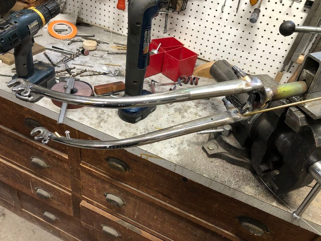
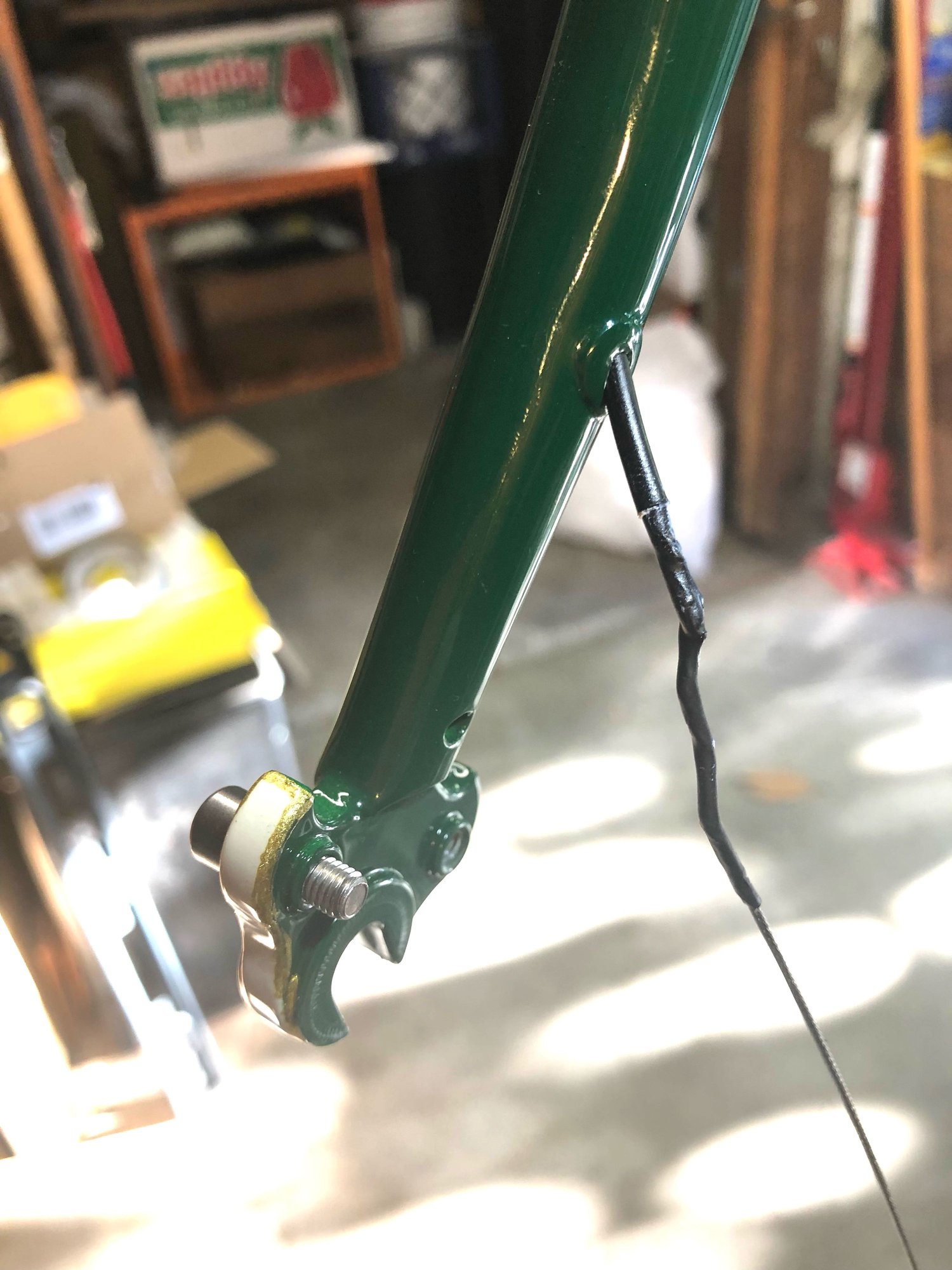
Speaking of internal wiring, if I can squeeze in here... how would you solve this problem? I need to get a coax lighting wire through both ends of a fork. The builder, a certain mumble-mumble bike butcher in Portland, gave me convenient holes near the tip of fork and up near the crown. I can pass the wire in near the crown, but need to catch it and pull out through the hole near the axle. I got lucky, once, with some derailleur cable and a loop from some hemp twine, and managed to catch the cable down low and draw it out of the fork. It looked like this:

and this:

But alas, the cable came out when I tried using it to draw the Schmidt coax cable through (more lube next time!). And now, for the life of me, I can't grab the cable like I did the first time. How would you snatch the cable coming down inside the fork at the lower hole?
and this:
But alas, the cable came out when I tried using it to draw the Schmidt coax cable through (more lube next time!). And now, for the life of me, I can't grab the cable like I did the first time. How would you snatch the cable coming down inside the fork at the lower hole?
08-25-21, 07:45 PM
#59
Randomhead
Join Date: Aug 2008
Location: Happy Valley, Pennsylvania
Posts: 24,383
Mentioned: 0 Post(s)
Tagged: 0 Thread(s)
Quoted: 4 Post(s)
Liked 3,684 Times
in
2,508 Posts
the traditional way is to pass a string through and use a vacuum to pull it.
I just did this on my lathe. For some reason, I had been avoiding that obvious method even though I kept thinking about it.
I just did this on my lathe. For some reason, I had been avoiding that obvious method even though I kept thinking about it.
Likes For unterhausen:
08-25-21, 08:24 PM
#60
This wrench fits...
Well, I just solved my own issue, sometimes it needs stating out loud for inspiration to come. I realized it might be easier to "steer" the derailleur cable from above if I put a nice bend in the cable down at the lower end, maybe 30 degrees. And sure enough, I was able to get the cable end to come right out the bottom port with just some slight twisting as it got close. Too easy! I used heat shrink to bind the cable and an exposed core of the coax wire to each other. Alert here for gugie
Likes For BoltBreaker:


