


B&M Toplight Line Brake Plus electrical connections
 06-30-21, 03:08 PM
#1
Senior Member
Thread Starter

Join Date: Oct 2015
Location: San Diego, California
Posts: 4,077
Bikes: Velo Orange Piolet
Mentioned: 28 Post(s)
Tagged: 0 Thread(s)
Quoted: 2228 Post(s)
Liked 2,011 Times
in
972 Posts
B&M Toplight Line Brake Plus electrical connections
So apparently the polarity is critical, but I don't know to determine the polarity of the current (coming from the headlight, B&M IQ-X). In between the connections (bottom right below) is a switch - does that toggle the polarity?
So if I hook it up and it doesn't work, flip that switch and see if it works? (can't find any instructions for this thing)
edit: ok Peter White's website says the "switch" between the connection spades locks the wires in if you don't use the connection spades and just stick the bare wires into those little holes instead. But now I have to figure out the polarity of the wires coming out of the headlight.
edit: On the headlight there are 2 short wires with spade connecters coming out to be connected to the taillight wire. One of those spade connectors has more plastic covering - I assumed that one is the positive so I hooked up the taillight with that assumption. Seems to work.
Last edited by tyrion; 06-30-21 at 04:39 PM.
 06-30-21, 06:39 PM
#2
Senior Member
Join Date: Aug 2010
Location: Madison, WI
Posts: 11,177
Bikes: 1961 Ideor, 1966 Perfekt 3 Speed AB Hub, 1994 Bridgestone MB-6, 2006 Airnimal Joey, 2009 Thorn Sherpa, 2013 Thorn Nomad MkII, 2015 VO Pass Hunter, 2017 Lynskey Backroad, 2017 Raleigh Gran Prix, 1980s Bianchi Mixte on a trainer. Others are now gone.
Mentioned: 47 Post(s)
Tagged: 0 Thread(s)
Quoted: 3453 Post(s)
Liked 1,453 Times
in
1,132 Posts
I thought that the light did not have a polarity issue, but if it does just switch the wires if it does not work.
Do not do what a friend of mine did, he was riding in front of me and he said he wanted to know if his taillight got brighter and asked me to watch it, I said ok. He then slammed on the brakes and I almost hit him.
Slightly off topic, but I have that same light but without the brake light feature. The nuts rusted onto the bolts and I tried to remove it from my rack, and the bolts turned under that much torque and mangled the plastic. I had to cut open the plastic housing to remove the bolts and replace them with stainless and glue that thing together again. My life might have been simpler if I had used stainless nuts in the first place.
Last edited by Tourist in MSN; 06-30-21 at 06:44 PM.
Likes For Tourist in MSN:
06-30-21, 07:22 PM
#3
Clark W. Griswold
Join Date: Mar 2014
Location: ,location, location
Posts: 13,467
Bikes: Foundry Chilkoot Ti W/Ultegra Di2, Salsa Timberjack Ti, Cinelli Mash Work RandoCross Fun Time Machine, 1x9 XT Parts Hybrid, Co-Motion Cascadia, Specialized Langster, Phil Wood Apple VeloXS Frame (w/DA 7400), R+M Supercharger2 Rohloff, Habanero Ti 26
Mentioned: 54 Post(s)
Tagged: 0 Thread(s)
Quoted: 4335 Post(s)
Liked 3,958 Times
in
2,646 Posts
When we were installing mine we did swap wires once but I don't remember which was which but I might be able to take pictures that probably may not help. It works fine and have had zero issues since I set it up.
Likes For veganbikes:
06-30-21, 07:41 PM
#4
Senior Member
Thread Starter
Join Date: Oct 2015
Location: San Diego, California
Posts: 4,077
Bikes: Velo Orange Piolet
Mentioned: 28 Post(s)
Tagged: 0 Thread(s)
Quoted: 2228 Post(s)
Liked 2,011 Times
in
972 Posts
I placed my wired up rear light in the front basket and road around to test the brake light feature. It works.
And I remember your post about rusted bolts - I'll grease them up when I mount it.
And I remember your post about rusted bolts - I'll grease them up when I mount it.
I thought that the light did not have a polarity issue, but if it does just switch the wires if it does not work.
Do not do what a friend of mine did, he was riding in front of me and he said he wanted to know if his taillight got brighter and asked me to watch it, I said ok. He then slammed on the brakes and I almost hit him.
Slightly off topic, but I have that same light but without the brake light feature. The nuts rusted onto the bolts and I tried to remove it from my rack, and the bolts turned under that much torque and mangled the plastic. I had to cut open the plastic housing to remove the bolts and replace them with stainless and glue that thing together again. My life might have been simpler if I had used stainless nuts in the first place.
Do not do what a friend of mine did, he was riding in front of me and he said he wanted to know if his taillight got brighter and asked me to watch it, I said ok. He then slammed on the brakes and I almost hit him.
Slightly off topic, but I have that same light but without the brake light feature. The nuts rusted onto the bolts and I tried to remove it from my rack, and the bolts turned under that much torque and mangled the plastic. I had to cut open the plastic housing to remove the bolts and replace them with stainless and glue that thing together again. My life might have been simpler if I had used stainless nuts in the first place.
07-01-21, 04:13 AM
#5
Senior Member
Join Date: Aug 2010
Location: Madison, WI
Posts: 11,177
Bikes: 1961 Ideor, 1966 Perfekt 3 Speed AB Hub, 1994 Bridgestone MB-6, 2006 Airnimal Joey, 2009 Thorn Sherpa, 2013 Thorn Nomad MkII, 2015 VO Pass Hunter, 2017 Lynskey Backroad, 2017 Raleigh Gran Prix, 1980s Bianchi Mixte on a trainer. Others are now gone.
Mentioned: 47 Post(s)
Tagged: 0 Thread(s)
Quoted: 3453 Post(s)
Liked 1,453 Times
in
1,132 Posts
It is my understanding that the way the light knows when you are slowing down is lower frequency in the AC, but I could be wrong on that. If you have AC, you have no polarity.
07-01-21, 06:30 PM
#6
Senior Member

Join Date: Feb 2008
Location: Peoria, IL
Posts: 4,469
Mentioned: 86 Post(s)
Tagged: 0 Thread(s)
Quoted: 1827 Post(s)
Liked 3,367 Times
in
1,573 Posts
is the ground wire on the tail light connected to the ground wire on the headlight and/or dynamo?
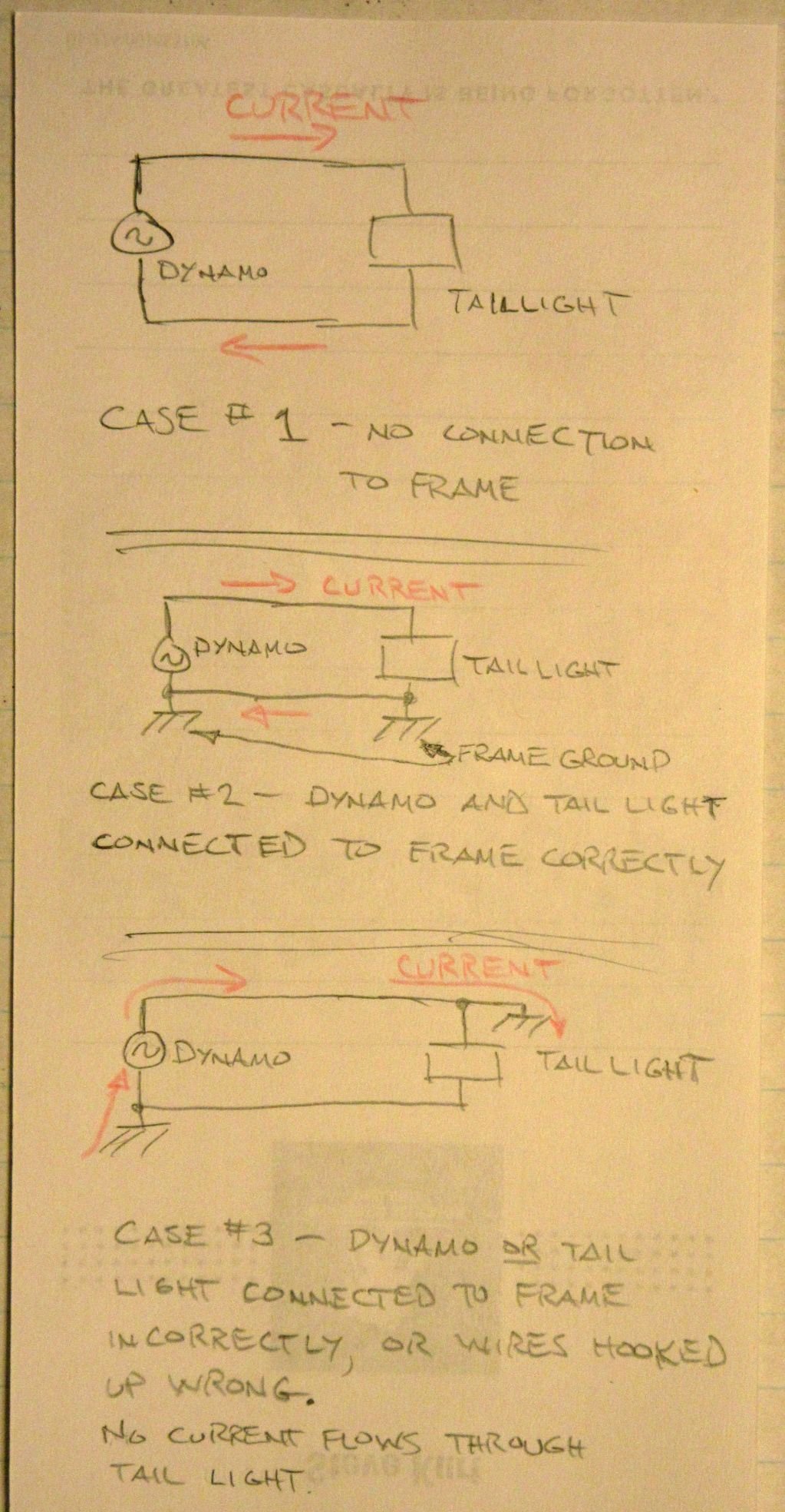
Sometimes B&M (and other manufacturers) connect one of the mounting bolts to one of the electrical connections. The same might be true of the headlight and dynamo. The idea is to make it easy to use the frame as one of the electrical conductors, and there may be some sort of ground symbol next to the bolt or electrical connection.
If the same wire doesn't go to the grounded electrical contacts at each end, it is possible to have the effect of allowing the current to flow around the tail light instead of through it.
a quick, lousy illustration of this issue....
Steve in Peoria
Likes For steelbikeguy:
07-01-21, 06:42 PM
#7
Senior Member
Thread Starter
Join Date: Oct 2015
Location: San Diego, California
Posts: 4,077
Bikes: Velo Orange Piolet
Mentioned: 28 Post(s)
Tagged: 0 Thread(s)
Quoted: 2228 Post(s)
Liked 2,011 Times
in
972 Posts
Thanks I got it sorted out. There were 2 short wires coming out of the headlight to be connected to longer wires to the taillight, and the polarity the wires at the headlight wasn't obvious. Took a guess as to polarity, connected it up, and it worked.
No obvious grounding points anywhere (these are modern lights).
No obvious grounding points anywhere (these are modern lights).
is the ground wire on the tail light connected to the ground wire on the headlight and/or dynamo?
Sometimes B&M (and other manufacturers) connect one of the mounting bolts to one of the electrical connections. The same might be true of the headlight and dynamo. The idea is to make it easy to use the frame as one of the electrical conductors, and there may be some sort of ground symbol next to the bolt or electrical connection.
If the same wire doesn't go to the grounded electrical contacts at each end, it is possible to have the effect of allowing the current to flow around the tail light instead of through it.
a quick, lousy illustration of this issue....
Steve in Peoria
07-01-21, 07:28 PM
#8
Senior Member
Join Date: Aug 2010
Location: Madison, WI
Posts: 11,177
Bikes: 1961 Ideor, 1966 Perfekt 3 Speed AB Hub, 1994 Bridgestone MB-6, 2006 Airnimal Joey, 2009 Thorn Sherpa, 2013 Thorn Nomad MkII, 2015 VO Pass Hunter, 2017 Lynskey Backroad, 2017 Raleigh Gran Prix, 1980s Bianchi Mixte on a trainer. Others are now gone.
Mentioned: 47 Post(s)
Tagged: 0 Thread(s)
Quoted: 3453 Post(s)
Liked 1,453 Times
in
1,132 Posts
Just in case someone reads this thread later so that they can figure out how to wire up their circuit:
DO NOT WIRE A TAILLIGHT DIRECTLY TO A DYNOHUB AS SHOWN IN THE DRAWINGS IN THE TWO PREVIOUS POSTS ! ! !
Most taillights do not have the overvoltage protection needed, but the headlights do. Thus, you wire the taillight to the headlight, that way the headlight protects the taillight from overvoltage as the taillight power comes through the headlight circuitry. The overvoltage occurs when you go down a hill at higher speed. The headlight instructions should tell you how to wire your taillight to the headlight.
Instead think of the above drawings as showing headlights, not taillights, then it would be correct.
Likes For Tourist in MSN:
07-02-21, 07:14 AM
#9
Senior Member
Join Date: Feb 2008
Location: Peoria, IL
Posts: 4,469
Mentioned: 86 Post(s)
Tagged: 0 Thread(s)
Quoted: 1827 Post(s)
Liked 3,367 Times
in
1,573 Posts
Just in case someone reads this thread later so that they can figure out how to wire up their circuit:
DO NOT WIRE A TAILLIGHT DIRECTLY TO A DYNOHUB AS SHOWN IN THE DRAWINGS IN THE TWO PREVIOUS POSTS ! ! !
Instead think of the above drawings as showing headlights, not taillights, then it would be correct.
DO NOT WIRE A TAILLIGHT DIRECTLY TO A DYNOHUB AS SHOWN IN THE DRAWINGS IN THE TWO PREVIOUS POSTS ! ! !
Instead think of the above drawings as showing headlights, not taillights, then it would be correct.
yeah... I noticed that too, after I drew it out.
 I did specify that it was a lousy drawing!
I thought it still made the point about the frame ground connections, but I'd hate to see someone use it as a guide to just power a tail light.
Steve in Peoria
07-02-21, 10:01 AM
#10
Senior Member
Join Date: Aug 2010
Location: Madison, WI
Posts: 11,177
Bikes: 1961 Ideor, 1966 Perfekt 3 Speed AB Hub, 1994 Bridgestone MB-6, 2006 Airnimal Joey, 2009 Thorn Sherpa, 2013 Thorn Nomad MkII, 2015 VO Pass Hunter, 2017 Lynskey Backroad, 2017 Raleigh Gran Prix, 1980s Bianchi Mixte on a trainer. Others are now gone.
Mentioned: 47 Post(s)
Tagged: 0 Thread(s)
Quoted: 3453 Post(s)
Liked 1,453 Times
in
1,132 Posts
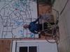
Photo below, I picked up a cheap ($10) dynohub wheel at a bike charity and put it on my errand bike, Shimano so it is grounded to the fork. I had a D Lumotec headlamp sitting on the shelf, the headlamp was made for bottle generators, thus no switch and grounded to the mounting bolt. Simplest wiring job I have ever done, hub grounded to the fork, light grounded to the fork, so only a single conductor wire was needed.

Light is too low to light up the road very well, but it is my errand bike so it is only ridden on well light city streets. Mostly used as a to-be-seen light, not a light to see with.
Likes For Tourist in MSN:
07-02-21, 10:21 AM
#11
Senior Member
Join Date: Feb 2008
Location: Peoria, IL
Posts: 4,469
Mentioned: 86 Post(s)
Tagged: 0 Thread(s)
Quoted: 1827 Post(s)
Liked 3,367 Times
in
1,573 Posts
.......
Photo below, I picked up a cheap ($10) dynohub wheel at a bike charity and put it on my errand bike, Shimano so it is grounded to the fork. I had a D Lumotec headlamp sitting on the shelf, the headlamp was made for bottle generators, thus no switch and grounded to the mounting bolt. Simplest wiring job I have ever done, hub grounded to the fork, light grounded to the fork, so only a single conductor wire was needed.
.
I still like the idea of block dynamos, such as this Jos that I bought in the 70's. Almost nothing to go wrong... other than the basic issues of incandescent bulbs and being driven by the tire.

The Schmidt hub dynamos with the connections at the end of the axle, and which mate to contacts at the fork dropout, are possibly as good as can be done with a hub dynamo.
Steve in Peoria
07-02-21, 12:50 PM
#12

aka Tom Reingold

Join Date: Jan 2009
Location: New York, NY, and High Falls, NY, USA
Posts: 40,498
Bikes: 1962 Rudge Sports, 1971 Raleigh Super Course, 1971 Raleigh Pro Track, 1974 Raleigh International, 1975 Viscount Fixie, 1982 McLean, 1996 Lemond (Ti), 2002 Burley Zydeco tandem
Mentioned: 511 Post(s)
Tagged: 0 Thread(s)
Quoted: 7345 Post(s)
Liked 2,452 Times
in
1,430 Posts
Bottle or hub dynamo, I found neither mystifying to hook up. The concept of polarity on an A/C circuit is a little confusing to me, but there are only so many combinations to try, and I eventually find a working one.
__________________
Tom Reingold, tom@noglider.com
New York City and High Falls, NY
Blogs: The Experienced Cyclist; noglider's ride blog
�When man invented the bicycle he reached the peak of his attainments.� � Elizabeth West, US author
Please email me rather than PM'ing me. Thanks.
Tom Reingold, tom@noglider.com
New York City and High Falls, NY
Blogs: The Experienced Cyclist; noglider's ride blog
�When man invented the bicycle he reached the peak of his attainments.� � Elizabeth West, US author
Please email me rather than PM'ing me. Thanks.
07-02-21, 10:01 PM
#13
Junior Member

Join Date: Jul 2015
Location: Memphis, TN
Posts: 196
Bikes: A few older US made Cannondales, a modern Soma Saga (no longer made, alas!), and one gifted crabon Specialized. Never enough.
Mentioned: 1 Post(s)
Tagged: 0 Thread(s)
Quoted: 45 Post(s)
Liked 60 Times
in
39 Posts
The little clip is to lock in loose wires to the openings, I believe. Confused me for some time as I use the connector lugs and I tossed the instructions.
Likes For But its me:
07-04-21, 11:42 AM
#14
Senior Member
Join Date: Feb 2008
Location: Peoria, IL
Posts: 4,469
Mentioned: 86 Post(s)
Tagged: 0 Thread(s)
Quoted: 1827 Post(s)
Liked 3,367 Times
in
1,573 Posts
As an electrical engineer, we don't really think about polarity for AC. Instead, we worry about phase angle, which is how much the sine waves of two different AC voltages differ. This is similar to how the sine and cosine function have the same shape, but the values are different for a given angle. This is a useful concept for electrical power transmission, which typically uses three sine waves spaced 120 degrees apart. For house wiring in the USA, we usually split the incoming 240VAC into two 120VAC voltages, but one is 180 degrees from the other. You can also think of this as one being an inverted version of the other.
Anyway... the problem isn't so much "polarity", it's that some lights and dynamos have one terminal connected to the bike frame (i.e. "grounded"), and this may not be well marked or documented. The ungrounded terminals of the dynamo and lights need to be connected together. Similarly, if you do want to run wires to the terminals that are connected to the frame, these all need to be connected together.
Failure to do this will mean that something is being shorted out, usually meaning that the lights won't illuminate.
Steve in Peoria
07-04-21, 01:59 PM
#15
aka Tom Reingold
Join Date: Jan 2009
Location: New York, NY, and High Falls, NY, USA
Posts: 40,498
Bikes: 1962 Rudge Sports, 1971 Raleigh Super Course, 1971 Raleigh Pro Track, 1974 Raleigh International, 1975 Viscount Fixie, 1982 McLean, 1996 Lemond (Ti), 2002 Burley Zydeco tandem
Mentioned: 511 Post(s)
Tagged: 0 Thread(s)
Quoted: 7345 Post(s)
Liked 2,452 Times
in
1,430 Posts
Thanks for all this. I'm with you so far.
I'm under the impression that the new stuff doesn't ground to the frame intentionally but might accidentally so that would be one reason you have to keep track of polarity. Is that right?
I'm under the impression that the new stuff doesn't ground to the frame intentionally but might accidentally so that would be one reason you have to keep track of polarity. Is that right?
__________________
Tom Reingold, tom@noglider.com
New York City and High Falls, NY
Blogs: The Experienced Cyclist; noglider's ride blog
�When man invented the bicycle he reached the peak of his attainments.� � Elizabeth West, US author
Please email me rather than PM'ing me. Thanks.
Tom Reingold, tom@noglider.com
New York City and High Falls, NY
Blogs: The Experienced Cyclist; noglider's ride blog
�When man invented the bicycle he reached the peak of his attainments.� � Elizabeth West, US author
Please email me rather than PM'ing me. Thanks.
07-04-21, 02:15 PM
#16
Senior Member
Thread Starter
Join Date: Oct 2015
Location: San Diego, California
Posts: 4,077
Bikes: Velo Orange Piolet
Mentioned: 28 Post(s)
Tagged: 0 Thread(s)
Quoted: 2228 Post(s)
Liked 2,011 Times
in
972 Posts
FWIW, the front light has no polarity indicators and is clearly not grounded to anything (plastic mounting bracket). The rear light has polarity markings and has bolts coming out of the casing that could get grounded.
07-04-21, 05:25 PM
#18
Senior Member
Join Date: Feb 2008
Location: Peoria, IL
Posts: 4,469
Mentioned: 86 Post(s)
Tagged: 0 Thread(s)
Quoted: 1827 Post(s)
Liked 3,367 Times
in
1,573 Posts
Some B&M tail lights that I've worked on in the past had one mounting bolt attached internally to one electrical terminal. No idea if they've changed that practice or not. There was usually a small chassis ground symbol molded into the plastic to indicate which terminal was grounded, but it wasn't easy to see and could be overlooked by the average consumer.
In case I haven't mentioned it lately, I make my own dynamo headlights and tail lights, so don't get exposed to the commercially made stuff very much.
I wouldn't expect to see accidental connection of a terminal to the frame, though.
Steve in Peoria
07-04-21, 05:53 PM
#19

Zoom zoom zoom zoom bonk

Join Date: Sep 2006
Location: New Zealand
Posts: 4,624
Bikes: Giant Defy, Trek 1.7c, BMC GF02, Fuji Tahoe, Scott Sub 35, Kona Rove, Trek Verve+2
Mentioned: 6 Post(s)
Tagged: 0 Thread(s)
Quoted: 551 Post(s)
Liked 722 Times
in
366 Posts
https://en.bumm.de/fileadmin/user_upl...ng_IQ-X_RZ.pdf
Likes For znomit:
07-04-21, 06:07 PM
#20
Senior Member
Thread Starter
Join Date: Oct 2015
Location: San Diego, California
Posts: 4,077
Bikes: Velo Orange Piolet
Mentioned: 28 Post(s)
Tagged: 0 Thread(s)
Quoted: 2228 Post(s)
Liked 2,011 Times
in
972 Posts
It's covered in the instructions:Black lead: current (+) / black-white lead: earth (�).
https://en.bumm.de/fileadmin/user_upl...ng_IQ-X_RZ.pdf
https://en.bumm.de/fileadmin/user_upl...ng_IQ-X_RZ.pdf
07-09-21, 10:41 AM
#21
Senior Member
Join Date: Apr 2005
Location: Ann Arbor, MI
Posts: 16,866
Bikes: 1980 Masi, 1984 Mondonico, 1984 Trek 610, 1980 Woodrup Giro, 2005 Mondonico Futura Leggera ELOS, 1967 PX10E, 1971 Peugeot UO-8
Mentioned: 49 Post(s)
Tagged: 0 Thread(s)
Quoted: 1854 Post(s)
Liked 661 Times
in
504 Posts
In your picture, there is a "plus" and "minus" molded into the plastic housing of your tail lamp, one near each of the spade lugs you mentioned. I'm pretty sure those were not randomly chosen by the B+M electrical engineer.
07-09-21, 10:48 AM
#22
Senior Member
Join Date: Apr 2005
Location: Ann Arbor, MI
Posts: 16,866
Bikes: 1980 Masi, 1984 Mondonico, 1984 Trek 610, 1980 Woodrup Giro, 2005 Mondonico Futura Leggera ELOS, 1967 PX10E, 1971 Peugeot UO-8
Mentioned: 49 Post(s)
Tagged: 0 Thread(s)
Quoted: 1854 Post(s)
Liked 661 Times
in
504 Posts
I haven't opened up a commercially built light in a while.
Some B&M tail lights that I've worked on in the past had one mounting bolt attached internally to one electrical terminal. No idea if they've changed that practice or not. There was usually a small chassis ground symbol molded into the plastic to indicate which terminal was grounded, but it wasn't easy to see and could be overlooked by the average consumer.
In case I haven't mentioned it lately, I make my own dynamo headlights and tail lights, so don't get exposed to the commercially made stuff very much.
I wouldn't expect to see accidental connection of a terminal to the frame, though.
Steve in Peoria
07-09-21, 12:02 PM
#24
Senior Member
Join Date: Feb 2008
Location: Peoria, IL
Posts: 4,469
Mentioned: 86 Post(s)
Tagged: 0 Thread(s)
Quoted: 1827 Post(s)
Liked 3,367 Times
in
1,573 Posts
Steve, I recall some of the linear taillights had some special features, like sequential firing ot the LEDs as a function of speed, and flashing as speed was shown to decrease, a cheap n dirty brake light function. The speed info could have been decoded from the AC power wavform just by counting zero crossings and the circuit for that could have been in the taillight or in the headlight, but do you think that would require enforcing a polarity between the head and tail lights, or perhaps polarity relative to the dyno? It might be some sort of data transfer is in play, which needs a signal reference in common. OTOH I doubt any signal levels are being measured, just zero crossings, which of course meter time.
In my tail lights, I usually just use one half of the AC voltage waveform, and the flashing is noticeable at slow speeds. A friend once asked if this was intentionally used as a way to grab the attention of other road users, and I was a bit sad to admit that it wasn't a clever bit of engineering.
Steve in Peoria
