


Widening a hub
 07-20-18, 08:13 AM
#1
Engineer
Thread Starter
Join Date: May 2010
Location: Bucharest, Romania, Europe
Posts: 591
Bikes: 1989 Krapf (with Dura-ace) road bike, 1973 Sputnik (made by XB3) road bike , 1961 Peugeot fixed gear, 2010 Trek 4400
Mentioned: 1 Post(s)
Tagged: 0 Thread(s)
Quoted: 38 Post(s)
Likes: 0
Liked 0 Times
in
0 Posts
Widening a hub
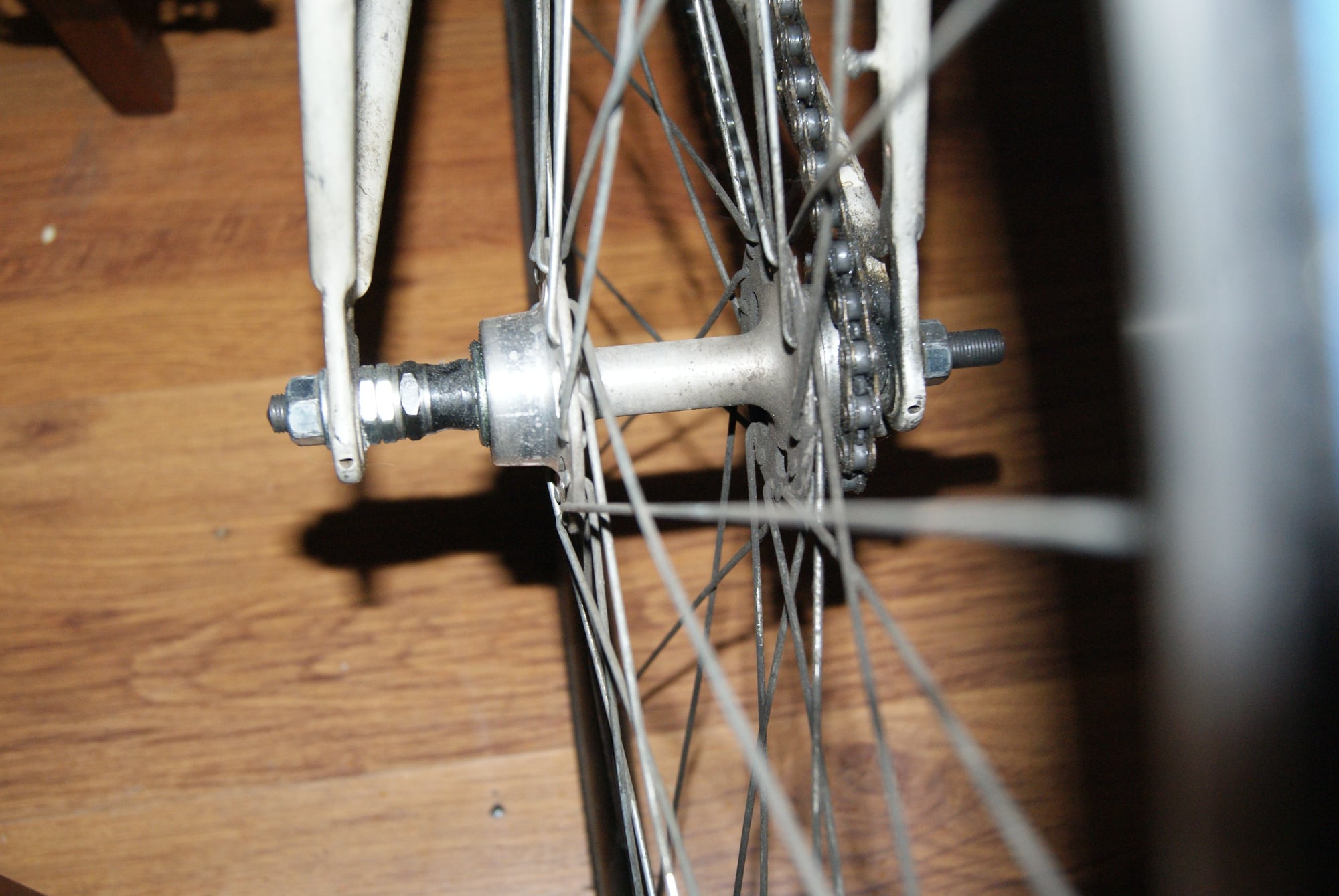
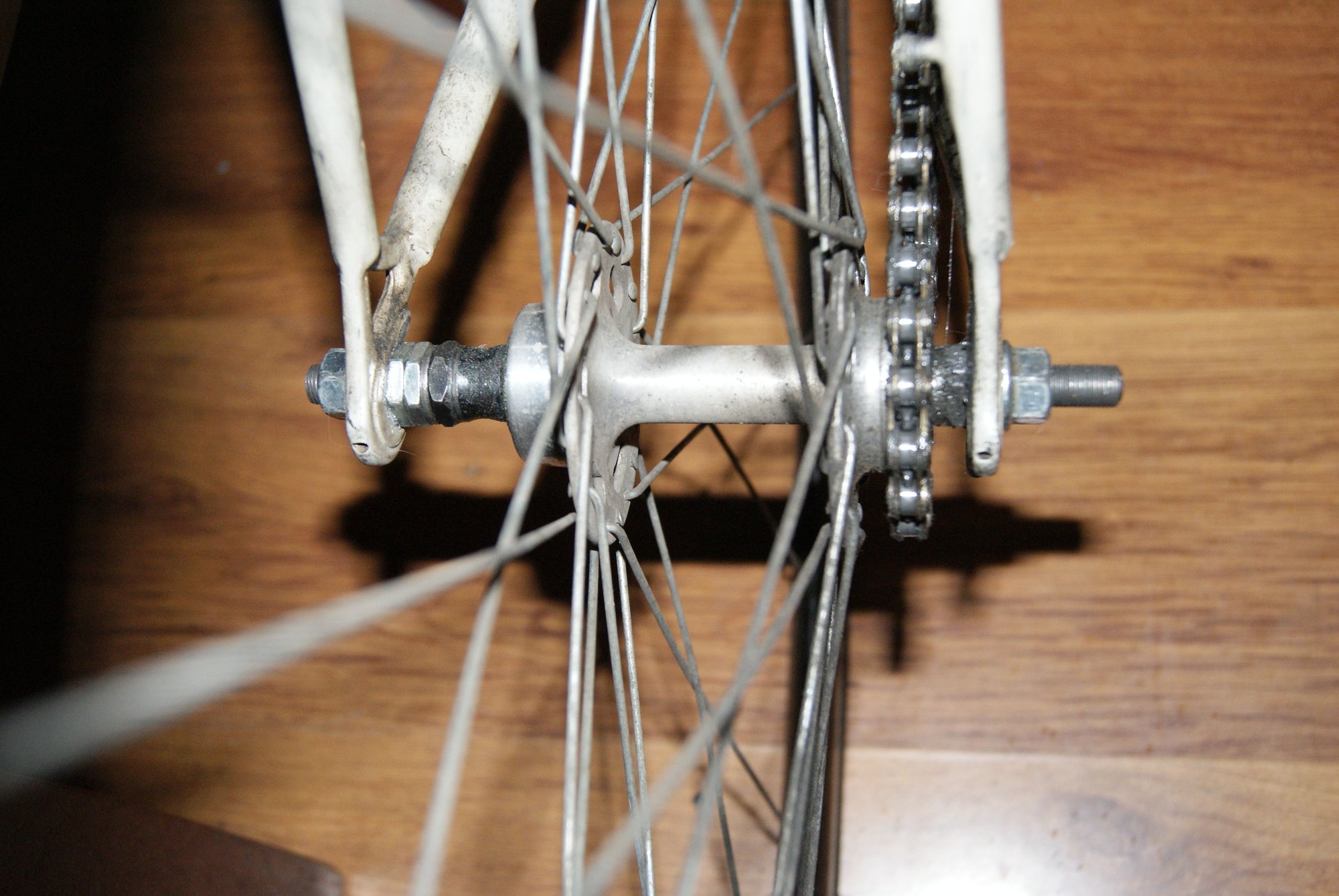
I'd like to widen a rear fixed hub by cutting it in the middle, attach a spacer in the middle and reconnect the two halves back by some method (threading, pressfit, splines, epoxy, welding). The reason for this is to increase the angle of the NDS spokes. Current hub is very short for 126mm OLD with a road freewheel up to 8 speed. I've installed fixed gear cog on that and moved the hub to get a nice chainline which happens to be quite near the dropout. I have about 30mm of spacers on NDS and it's bending axles a lot. NDS spokes are almost vertical even if the wheel is about 5mm offcenter near the DS (i don't have rear brake so it's not bothering at all). If I would try to align the wheel to sit center in frame the NDS spokes will be dead vertical or go into negative angle (NDS spoke flange is about center between dropouts)
The hub in question is an old shimano high flange HC-110 (before anyone saying not to cannibalize this vintage hub - the QR and axle is missing, i got a generic solid axle for it, i have cut reverse threads for the fixed lockring already so it's not a pristine matching pair of vintage hub, but a shell of a rear hub with some modifications done to it and further plan to modify it)
The caveats are more likely miss-aligning the cups both in angle or concentricty - I'll do whatever it takes to get them aligned good (in a lathe, dial indicators, etc - or even better, remove the cups and cut shoulders for a standard bearing with a custom made axle for it.. after it's welded or something the lathe should ensure perfect concentricty and gripping the threads on the DS will ensure a very true axis of rotation in relation to the rear cog - that's another project.. I'll see how it turns out and make a decision afterwards about converting to bearings)
I know it's doable but I'm wondering a few things:
- Does the NDS spoke flange get any torsion from the rear pinion? (if not i could go for pressfit and carefully lathed down would be quick, neat, great looking; If not then something stiff must be added to resist torsion threads or welding - probably I'll go press-fit and do some welding afterward) - i have a few theories about this like it does but in small percentage. To transmit anything the DS spokes must shift from the rim a fraction so the much stronger shell can transmit with the NDS spokes)
- Has anyone done this thing before? (maybe for some DIY fat bikes or something)
This is just a project of mine. I know that I can squeeze the frame to better support the axle near the NDS bearing by removing the spacers and bend only the left triangle (but this is so wrong! i don't want to touch the frame, the frame is aligned and want to keep it that way), or that I could go with a fixed gear hub that has symmetrical flanges from the center-line and it's a solid option (idk about 126OLD for fixed gear but spacers can be put to get from 120mm.. yet this leaves me in the same axle-bending situation), or get a fixed gear/track frame with correct OLD with correct hub. I'd like to make this work and I enjoy machining parts.. so no biggie in terms of cost or hassle.
Thank you, would like an opinion before I go for it - hence this thread.
 07-20-18, 08:26 AM
#2

Senior member

Join Date: Oct 2004
Location: Oakville Ontario
Posts: 8,125
Mentioned: 25 Post(s)
Tagged: 0 Thread(s)
Quoted: 946 Post(s)
Liked 664 Times
in
376 Posts
I don't have the answer for you but @Curtis Odom might be able to guide you. He builds hubs with separate flanges and sleeves and certainly knows how to graft them together.
I don't think Curtis has been active on the forum lately, but I am in contact with him from time to time, so he is still around.
I don't think Curtis has been active on the forum lately, but I am in contact with him from time to time, so he is still around.
07-20-18, 09:08 AM
#3
Banned
have pictures of your home machine shop to do this? a lathe seems a minimal requirement
for single speed MTB there are 135 wide hubs . made ... TW..
now with fat bike cruisers even wider hubs are made ..
....
for single speed MTB there are 135 wide hubs . made ... TW..
now with fat bike cruisers even wider hubs are made ..
....
07-20-18, 09:18 AM
#4
Banned
I have used a very strong axle design in a hub from US manufacturer's; Bullseye* (closed)
and Phil Wood, (still in San Jose California) the axles so much larger in thickness, than shimano's 10mm..
and its thick in the center , between the bearing races..
Its just inside of the drive side cone that common freewheel hubs break..
* machined hub flanges drilled for spokes screw onto a tube,
supports cartridge bearings outside Diameter.
axle end caps , bearings and spacers ,
around an axle thru the bearing ID is on the inside
it is reduced on the very ends to fit in the dropout width
bearing number is 6001..
tightening the QR compresses the stack to hold the end caps on ..
there are just small set screws so it does not come apart
when you take the wheel out..
...
Last edited by fietsbob; 07-20-18 at 09:35 AM.
07-20-18, 09:07 PM
#5
Nigel
Join Date: Mar 2011
Location: San Jose, CA
Posts: 2,991
Bikes: 1980s and 1990s steel: CyclePro, Nishiki, Schwinn, SR, Trek........
Mentioned: 12 Post(s)
Tagged: 0 Thread(s)
Quoted: 384 Post(s)
Likes: 0
Liked 6 Times
in
6 Posts
...... the lathe should ensure perfect concentricty and gripping the threads on the DS will ensure a very true axis of rotation in relation to the rear cog - that's another project.. I'll see how it turns out and make a decision afterwards about converting to bearings)......
If you have access to the equipment to do this project properly, you can more easily just make a new hub with the geometry you desire.
There is torque fed from one side to the other because neither the spokes nor the hub are infinitely rigid. Spokes less rigid, and that results in torque through the hub to the NDS flange.
07-20-18, 09:58 PM
#6
Senior Member

Join Date: Nov 2014
Location: Eugene, Oregon, USA
Posts: 27,548
Mentioned: 217 Post(s)
Tagged: 0 Thread(s)
Quoted: 18427 Post(s)
Liked 4,544 Times
in
3,376 Posts
There are several manufacturers that have used a carbon fiber sleeve connected to two aluminum or titanium flanges.
Nuke Proof?
Apparently their biggest issue was broken flanges, not a slipping sleeve.
If I was doing it I'd probably design it so your sleeve fits over the top of the hub spindle/shaft. Perhaps cut a square stop near the flanges on both ends.
As noted for the CF, a tight fit and epoxy should be fine. Especially if you have about 1 1/2 inches of overlap on both sides.
Getting them precisely true would be an issue, but perhaps not bad if you have quite a bit of overlap.
I'd probably first chuck up the uncut hub in your lathe, and clean up the center shaft before cutting (square, uniform thickness, stops on ends). Then cut, epoxy, and press back together with a properly sized tube of 6061 or 7xxx.
Give yourself just enough play that you don't bend anything when pressing together.
You might be able to weld, but some types of cast aluminum weld poorly, and it may well not be necessary, especially with lots of overlap and a good epoxy joint. Also, weld heat could be an issue.
Keep in mind that the two flanges are twisted 1/2 spoke to each other.
You could radial lace the NDS, but I'd probably just do the same cross pattern on both sides because of the potential of issues with radial lacing old hubs.
07-20-18, 10:41 PM
#7
Senior Member
Join Date: Jan 2013
Location: Llano Estacado
Posts: 3,702
Bikes: old clunker
Mentioned: 13 Post(s)
Tagged: 0 Thread(s)
Quoted: 684 Post(s)
Likes: 0
Liked 105 Times
in
83 Posts
Why so indirect? If the problem is bent axles, wouldn't the direct solution be to get a stronger axle?
07-21-18, 04:59 AM
#8
Engineer
Thread Starter
Join Date: May 2010
Location: Bucharest, Romania, Europe
Posts: 591
Bikes: 1989 Krapf (with Dura-ace) road bike, 1973 Sputnik (made by XB3) road bike , 1961 Peugeot fixed gear, 2010 Trek 4400
Mentioned: 1 Post(s)
Tagged: 0 Thread(s)
Quoted: 38 Post(s)
Likes: 0
Liked 0 Times
in
0 Posts
First of all NOTHING is perfect, we are humans (well most are), not GOD.
If you have access to the equipment to do this project properly, you can more easily just make a new hub with the geometry you desire.
There is torque fed from one side to the other because neither the spokes nor the hub are infinitely rigid. Spokes less rigid, and that results in torque through the hub to the NDS flange.
I don't have the answer for you but @Curtis Odom might be able to guide you. He builds hubs with separate flanges and sleeves and certainly knows how to graft them together.
I don't think Curtis has been active on the forum lately, but I am in contact with him from time to time, so he is still around.
I don't think Curtis has been active on the forum lately, but I am in contact with him from time to time, so he is still around.
There are several manufacturers that have used a carbon fiber sleeve connected to two aluminum or titanium flanges.
Nuke Proof?
Apparently their biggest issue was broken flanges, not a slipping sleeve.
If I was doing it I'd probably design it so your sleeve fits over the top of the hub spindle/shaft. Perhaps cut a square stop near the flanges on both ends.
As noted for the CF, a tight fit and epoxy should be fine. Especially if you have about 1 1/2 inches of overlap on both sides.
Getting them precisely true would be an issue, but perhaps not bad if you have quite a bit of overlap.
I'd probably first chuck up the uncut hub in your lathe, and clean up the center shaft before cutting (square, uniform thickness, stops on ends). Then cut, epoxy, and press back together with a properly sized tube of 6061 or 7xxx.
Give yourself just enough play that you don't bend anything when pressing together.
You might be able to weld, but some types of cast aluminum weld poorly, and it may well not be necessary, especially with lots of overlap and a good epoxy joint. Also, weld heat could be an issue.
Keep in mind that the two flanges are twisted 1/2 spoke to each other.
You could radial lace the NDS, but I'd probably just do the same cross pattern on both sides because of the potential of issues with radial lacing old hubs.
Nuke Proof?
Apparently their biggest issue was broken flanges, not a slipping sleeve.
If I was doing it I'd probably design it so your sleeve fits over the top of the hub spindle/shaft. Perhaps cut a square stop near the flanges on both ends.
As noted for the CF, a tight fit and epoxy should be fine. Especially if you have about 1 1/2 inches of overlap on both sides.
Getting them precisely true would be an issue, but perhaps not bad if you have quite a bit of overlap.
I'd probably first chuck up the uncut hub in your lathe, and clean up the center shaft before cutting (square, uniform thickness, stops on ends). Then cut, epoxy, and press back together with a properly sized tube of 6061 or 7xxx.
Give yourself just enough play that you don't bend anything when pressing together.
You might be able to weld, but some types of cast aluminum weld poorly, and it may well not be necessary, especially with lots of overlap and a good epoxy joint. Also, weld heat could be an issue.
Keep in mind that the two flanges are twisted 1/2 spoke to each other.
You could radial lace the NDS, but I'd probably just do the same cross pattern on both sides because of the potential of issues with radial lacing old hubs.
I figured a picture worths 1000 words so here they are.
 07-21-18, 06:40 PM
#9
Senior Member
Join Date: Feb 2012
Location: Rochester, NY
Posts: 18,143
Bikes: Stewart S&S coupled sport tourer, Stewart Sunday light, Stewart Commuting, Stewart Touring, Co Motion Tandem, Stewart 3-Spd, Stewart Track, Fuji Finest, Mongoose Tomac ATB, GT Bravado ATB, JCP Folder, Stewart 650B ATB
Mentioned: 0 Post(s)
Tagged: 0 Thread(s)
Quoted: 4233 Post(s)
Liked 3,942 Times
in
2,349 Posts
So with the modded fixed gear configuration which side of the rear axle is bending? I see the flange to center having been shifted opposite from the usual, the RH side is more then the LH side is. So one would think that the axle bending is now just inboard of the LH cone. Is this so?
I don't think changing the flange to flange dimension will gain you much, WRT axle bending if the flange to center off set isn't balanced. Andy
I don't think changing the flange to flange dimension will gain you much, WRT axle bending if the flange to center off set isn't balanced. Andy
__________________
AndrewRStewart
AndrewRStewart
 07-22-18, 03:42 AM
#10
Engineer
Thread Starter
Join Date: May 2010
Location: Bucharest, Romania, Europe
Posts: 591
Bikes: 1989 Krapf (with Dura-ace) road bike, 1973 Sputnik (made by XB3) road bike , 1961 Peugeot fixed gear, 2010 Trek 4400
Mentioned: 1 Post(s)
Tagged: 0 Thread(s)
Quoted: 38 Post(s)
Likes: 0
Liked 0 Times
in
0 Posts
As I said, axle is bending NDS where the massive spacers are put. Not only the axle is bending, but the NDS spokes are having a near vertical angle, which is bad in terms of lateral stiffness. By increasing flange to flange dimension will center the flanges in the dropouts. Will make the NDS bearing sitting closer to the dropout so less bending issues, Will increase angle of the spokes improving lateral stiffness.
The bike is ride-able in this way.. i change axles every few months (and cones since from the bending they take the punch and wear rapidly)
I'll probably have to realign the dropouts from time to time.
So in a sketch this is current situation, and this is what I try to achieve.
The bike is ride-able in this way.. i change axles every few months (and cones since from the bending they take the punch and wear rapidly)
I'll probably have to realign the dropouts from time to time.
So in a sketch this is current situation, and this is what I try to achieve.
07-22-18, 08:43 AM
#11
Senior Member

Join Date: Aug 2015
Posts: 3,339
Mentioned: 39 Post(s)
Tagged: 0 Thread(s)
Quoted: 1151 Post(s)
Liked 1,790 Times
in
980 Posts
Your configuration looks really far over, is your frame straight? Are your dropouts aligned?
If this was my only option I would take out the spacers and coldset to 120.
If this was my only option I would take out the spacers and coldset to 120.
07-22-18, 10:15 AM
#12
Engineer
Thread Starter
Join Date: May 2010
Location: Bucharest, Romania, Europe
Posts: 591
Bikes: 1989 Krapf (with Dura-ace) road bike, 1973 Sputnik (made by XB3) road bike , 1961 Peugeot fixed gear, 2010 Trek 4400
Mentioned: 1 Post(s)
Tagged: 0 Thread(s)
Quoted: 38 Post(s)
Likes: 0
Liked 0 Times
in
0 Posts
Well.. this is a project bike. The road everything conversion. So it's a road frame, road bar (flop and chop), road hubs. The only track/fixie specific is the rear cog, chain and crank (1/8 50t 130BCD)
Because i can't push the chainring (50T can't sit sit closer to the frame.. atm it has about 7mm clearance to chainstay.. i can cut that to 3mm with shorter BB but i think it sits just fine as is), the chainline is set at 46mm instead of normal track at 40-42mm. Beacuse of that, this road hub (that was meant to have a long freewheel on it) is pushed far to the right to achieve this 46mm chainline - this gets the hub shifted so far to the right. I've put the wheel about 5-10mm to the right (it does not sit center in the frame) to gain some lateral strength as if it sat center the nds spokes were too close to vertical which is really not good. Now at 5th axle change i want to put a stop to this.
A fixed gear hub is meant to have 42 or so chainline so even with a new hub i'd have to push it to the right a bit for 46 chainline. The crazy idea a LBS told me is to coldset only the left triangle to get rid of those spacers (but this does not solve the offcenter wheel, or the NDS spoke angle) I said no way. this is a kludge to purposely coldset misaligned frame.
Other ideas would be another hub but with 46mm chainline for fixed gear or single speed but is just a unicorn of a hub. So i plan to make my own.
07-22-18, 10:35 AM
#13
Banned
[Coffee in hand] I'm thinking a joining sleeve
and the splice over a cut, 'turnbuckle' threaded
mixing a right handed thread , and a left handed thread ,
so rotating the splice tube pulls the threaded cut sections together , it self being a matching thread,
with an internal shoulder to match the 2 pieces being joined and having them well aligned
when all 3 butt together will have a raised ring in the center...
Classic 'screwed and glued' AlAn Frames were machined in a similar manner ,
rotating the frame tubes pulled the 'lug' ends together, they being threaded,
while epoxy was still yet to cure.
Violin Chin rest clamps are another place where RH & LH thread is used on a sleeve nut
pulling the clamp tighter..
....
07-22-18, 11:15 AM
#14
elcraft
Can you use a smaller Chain ring and smaller hub cog to keep the same ratio; but maybe move the chainwheel closer to the frame? Or perhaps obtain a 126 mm OLD Fixie/ SS hub for the project like:
https://www.treefortbikes.com/All-Ci...SABEgLxwfD_BwE
https://www.treefortbikes.com/All-Ci...SABEgLxwfD_BwE
07-22-18, 12:24 PM
#15
Engineer
Thread Starter
Join Date: May 2010
Location: Bucharest, Romania, Europe
Posts: 591
Bikes: 1989 Krapf (with Dura-ace) road bike, 1973 Sputnik (made by XB3) road bike , 1961 Peugeot fixed gear, 2010 Trek 4400
Mentioned: 1 Post(s)
Tagged: 0 Thread(s)
Quoted: 38 Post(s)
Likes: 0
Liked 0 Times
in
0 Posts
[Coffee in hand] I'm thinking a joining sleeve
and the splice over a cut, 'turnbuckle' threaded
mixing a right handed thread , and a left handed thread ,
so rotating the splice tube pulls the threaded cut sections together , it self being a matching thread,
with an internal shoulder to match the 2 pieces being joined and having them well aligned
when all 3 butt together will have a raised ring in the center...
Classic 'screwed and glued' AlAn Frames were machined in a similar manner ,
rotating the frame tubes pulled the 'lug' ends together, they being threaded,
while epoxy was still yet to cure.
Violin Chin rest clamps are another place where RH & LH thread is used on a sleeve nut
pulling the clamp tighter..
....
and the splice over a cut, 'turnbuckle' threaded
mixing a right handed thread , and a left handed thread ,
so rotating the splice tube pulls the threaded cut sections together , it self being a matching thread,
with an internal shoulder to match the 2 pieces being joined and having them well aligned
when all 3 butt together will have a raised ring in the center...
Classic 'screwed and glued' AlAn Frames were machined in a similar manner ,
rotating the frame tubes pulled the 'lug' ends together, they being threaded,
while epoxy was still yet to cure.
Violin Chin rest clamps are another place where RH & LH thread is used on a sleeve nut
pulling the clamp tighter..
....
Being RH and LH will make sure any way you torque the hub you can't transmit anything if it unscrews.
Turnbuckles are good for clamping without moving the two pieces that are being clamped - Like in a cable tie or applications you mentioned and other cases.
In this application, once tighten (with whatever threading) and epoxyed then the spokes will be like safety-wire keeping the hub from untwisting. I will remove the spokes to do the modification.
If I remember, there was a carbon hub with weird carbon spokes (a sheet of carbon with spoke like pattern either side) that used the hub as a way to tension the spokes by spreading flanges apart. (LE: found them, Mad Fiber wheels )
Lowering the chainline could be a good thing, but if i make my own modified hub then I can have better support (putting bearings very near to the dropouts), and very good side support from the spokes. And will certainly not run into clearance issues with any chainring in future.
As for connecting. Threads are rarely a good way to ensure concentricity. And hard to thread with a boring bar at that small diameter. Tapping it with normal taps and dies is inconvenient as I don't have such large taps, and the hub shell is 17.2mm on outside.. not enough for M18, too big for M16 (will remove too much material.. will have to measure but i expect the wall to be less than 2mm to work with). So a pressfit sleeve with some epoxy should do the trick. Also the angled spokes will keep the hub together by a lot of clamping provided by 36 spokes. (axial clamping between flanges i mean)
I'll do some further measuring, and start working by disassembly of spokes. Will do some calculations beforehand (clenching fingers for some CAD/CAE/FEA analysis). Thinking to upgrade the axle and the hub to sealed bearings. For the axle i think I can fit a 12mm axle (and filing two flats to enter the 10mm dropout. Would not like to file on these fine Campagnolo dropouts for my franken-hub). Will be back after some 3d modeling.
07-22-18, 04:17 PM
#16
Senior member
Join Date: Oct 2004
Location: Oakville Ontario
Posts: 8,125
Mentioned: 25 Post(s)
Tagged: 0 Thread(s)
Quoted: 946 Post(s)
Liked 664 Times
in
376 Posts
What would be the purpose for that? Threads must be both RH to transmit torque from DS to NDS in forward and both LH thread would be used to transmit torque in the other way (from DS to NDS but braking torque during skids).
Being RH and LH will make sure any way you torque the hub you can't transmit anything if it unscrews.
Turnbuckles are good for clamping without moving the two pieces that are being clamped - Like in a cable tie or applications you mentioned and other cases.
In this application, once tighten (with whatever threading) and epoxyed then the spokes will be like safety-wire keeping the hub from untwisting. I will remove the spokes to do the modification.
If I remember, there was a carbon hub with weird carbon spokes (a sheet of carbon with spoke like pattern either side) that used the hub as a way to tension the spokes by spreading flanges apart. (LE: found them, Mad Fiber wheels )
Lowering the chainline could be a good thing, but if i make my own modified hub then I can have better support (putting bearings very near to the dropouts), and very good side support from the spokes. And will certainly not run into clearance issues with any chainring in future.
As for connecting. Threads are rarely a good way to ensure concentricity. And hard to thread with a boring bar at that small diameter. Tapping it with normal taps and dies is inconvenient as I don't have such large taps, and the hub shell is 17.2mm on outside.. not enough for M18, too big for M16 (will remove too much material.. will have to measure but i expect the wall to be less than 2mm to work with). So a pressfit sleeve with some epoxy should do the trick. Also the angled spokes will keep the hub together by a lot of clamping provided by 36 spokes. (axial clamping between flanges i mean)
I'll do some further measuring, and start working by disassembly of spokes. Will do some calculations beforehand (clenching fingers for some CAD/CAE/FEA analysis). Thinking to upgrade the axle and the hub to sealed bearings. For the axle i think I can fit a 12mm axle (and filing two flats to enter the 10mm dropout. Would not like to file on these fine Campagnolo dropouts for my franken-hub). Will be back after some 3d modeling.
07-22-18, 05:03 PM
#17
Senior Member
Join Date: Nov 2014
Location: Eugene, Oregon, USA
Posts: 27,548
Mentioned: 217 Post(s)
Tagged: 0 Thread(s)
Quoted: 18427 Post(s)
Liked 4,544 Times
in
3,376 Posts
Nonetheless, if you fix the long axle issue, you may not need to worry about bending the axle.
Have you looked at adjusting the crankset?
- Narrower bottom bracket.
- Moving chainring to the inside of the spider rather than the outside (possibly adding a bashguard on the outside.
- etc.
07-22-18, 06:32 PM
#18
Senior Member
Join Date: Feb 2012
Location: Rochester, NY
Posts: 18,143
Bikes: Stewart S&S coupled sport tourer, Stewart Sunday light, Stewart Commuting, Stewart Touring, Co Motion Tandem, Stewart 3-Spd, Stewart Track, Fuji Finest, Mongoose Tomac ATB, GT Bravado ATB, JCP Folder, Stewart 650B ATB
Mentioned: 0 Post(s)
Tagged: 0 Thread(s)
Quoted: 4233 Post(s)
Liked 3,942 Times
in
2,349 Posts
I think you'll find that remanufacturing the hub is a lot bigger a task then getting a proper single speed crankset/BB is. The proper front set up will allow a closer to the stay ring and the resulting shift to the center of the bike of the rear cog placement. Additionally a spacer or two behind the rear cog will further offer up a couple more MMs of hubshell movement to the NDS.
BYW you say the hub is a standard road one? It looks like you're running a threaded cog and not a single cog freewheel. Is this so? If so I hope you run wheel brakes on this bike. Andy
BYW you say the hub is a standard road one? It looks like you're running a threaded cog and not a single cog freewheel. Is this so? If so I hope you run wheel brakes on this bike. Andy
__________________
AndrewRStewart
AndrewRStewart
07-22-18, 06:54 PM
#20
Senior Member
Join Date: Feb 2012
Location: Rochester, NY
Posts: 18,143
Bikes: Stewart S&S coupled sport tourer, Stewart Sunday light, Stewart Commuting, Stewart Touring, Co Motion Tandem, Stewart 3-Spd, Stewart Track, Fuji Finest, Mongoose Tomac ATB, GT Bravado ATB, JCP Folder, Stewart 650B ATB
Mentioned: 0 Post(s)
Tagged: 0 Thread(s)
Quoted: 4233 Post(s)
Liked 3,942 Times
in
2,349 Posts
I also agree. But since the hub issues are being driven by the crank/ring's chainline I referenced that first. One more example of having the wrong tools for the job. We see this stuff frequently with all the single cog/fixie conversions being done on the cheap. Andy
__________________
AndrewRStewart
AndrewRStewart
07-23-18, 03:07 AM
#21
Engineer
Thread Starter
Join Date: May 2010
Location: Bucharest, Romania, Europe
Posts: 591
Bikes: 1989 Krapf (with Dura-ace) road bike, 1973 Sputnik (made by XB3) road bike , 1961 Peugeot fixed gear, 2010 Trek 4400
Mentioned: 1 Post(s)
Tagged: 0 Thread(s)
Quoted: 38 Post(s)
Likes: 0
Liked 0 Times
in
0 Posts
I think you'll find that remanufacturing the hub is a lot bigger a task then getting a proper single speed crankset/BB is. The proper front set up will allow a closer to the stay ring and the resulting shift to the center of the bike of the rear cog placement. Additionally a spacer or two behind the rear cog will further offer up a couple more MMs of hubshell movement to the NDS.
BYW you say the hub is a standard road one? It looks like you're running a threaded cog and not a single cog freewheel. Is this so? If so I hope you run wheel brakes on this bike. Andy
BYW you say the hub is a standard road one? It looks like you're running a threaded cog and not a single cog freewheel. Is this so? If so I hope you run wheel brakes on this bike. Andy
Cranks are for single speed/track/fixie, Chainring is on the inside of the spider. I can shorten the BB by 4mm leaving a chainline of 42.. better but will get me more distance from the cog to the right dropout. Increasing chainline puts more stress over the BB and decreases stress on the right rear hub bearing (in this case it increases the loads on the NDS bearing since the hub moves as a whole... well.. i plan to change that.)
Many areas in a bike can be better engineered to better suit loads, and if implementation is not too hard* why not go for it? I think my engineering skills are up to the task of designing a better hub for my bike, afterall I R&D car parts for the last 10 years.
*clarification: each has it's own "hard" evaluation. For me a quick lathe job and some wheel-building does not seem such a wild thing to do. For others 3d CNC a block of Al is very doable, and for others anything involving a file is over their skills or confidence.
07-23-18, 03:42 AM
#22
Senior Member
Join Date: Nov 2014
Location: Eugene, Oregon, USA
Posts: 27,548
Mentioned: 217 Post(s)
Tagged: 0 Thread(s)
Quoted: 18427 Post(s)
Liked 4,544 Times
in
3,376 Posts
better but will get me more distance from the cog to the right dropout. Increasing chainline puts more stress over the BB and decreases stress on the right rear hub bearing (in this case it increases the loads on the NDS bearing since the hub moves as a whole... well.. i plan to change that.)
A goal of a short axle maximally supported by bearings is good.
However, moving the chainline more towards the middle of the axle should cause the load to be distributed between the right and left dropouts which may be of some benefit.
I put a FAT crank on my cargo bike, and the Q-Factor is far too wide for my comfort. I'm not quite sure what the optimal Q-Factor is, but in my opinion, narrow is good.
07-23-18, 09:34 AM
#23
Banned
[reply to 15th ] it was a how to thought (yesterday's coffee now needs a new cuppa, today.. )
the hub to spokes to rim power transmission remains unchanged ..
the center splice is pulled together solidly by the rotating the splice tube* then the epoxy cures
and it's a wider and solid hub.. Which I thought was the job..
* machine the inside of hex stock, perhaps?,, for a surface to grip outside, with a spanner.
good luck

