


Locking up a freehub
 04-02-24, 12:32 PM
#26
Newbie
Thread Starter
Join Date: Mar 2024
Posts: 21
Mentioned: 0 Post(s)
Tagged: 0 Thread(s)
Quoted: 15 Post(s)
Likes: 0
Liked 1 Time
in
1 Post
I agree with JohnDThompson
Being unfamiliar with this ratcheting mechanism or the e-motor this ratcheting mechanism is mounted to the output of...What are the odds that the ratchet drive ring will simply unscrew when reverse forces are applied?
It's gotta be a hardened steel of some sort. They can't possibly machine it in and harden locally, can they? The production process cost would be prohibitive. The ratchet ring has got to be a seperate piece and threaded in.
Tack welding in the drive ring would have to be a requirement contingent upon both being compatible weldable metals.
Failing that, why not machine a solid bushing and press it in to the output gear with a keyway and pin to dummy out the whole ratchet altogether?
Although I already mentioned that above, but I�ll say it again, one of the manufacturer�s considerations in designing this freewheel in the motor, is to be able to replace it later with a bushing to make a coaster brake compatible version, as they already did on the previous model.
As I�m not sure I�ll be able to procure the right bushing, I thought we could find a safe enough way, (even if more expensive) to lock the freewheel.
I wish I could machine a bushing myself, and I might be able to do something with a big aluminum washer that I put inner\outer keyways in. It would be a hassle, but you�re right, it should be the best and safest solution, if I can make it/procure it.
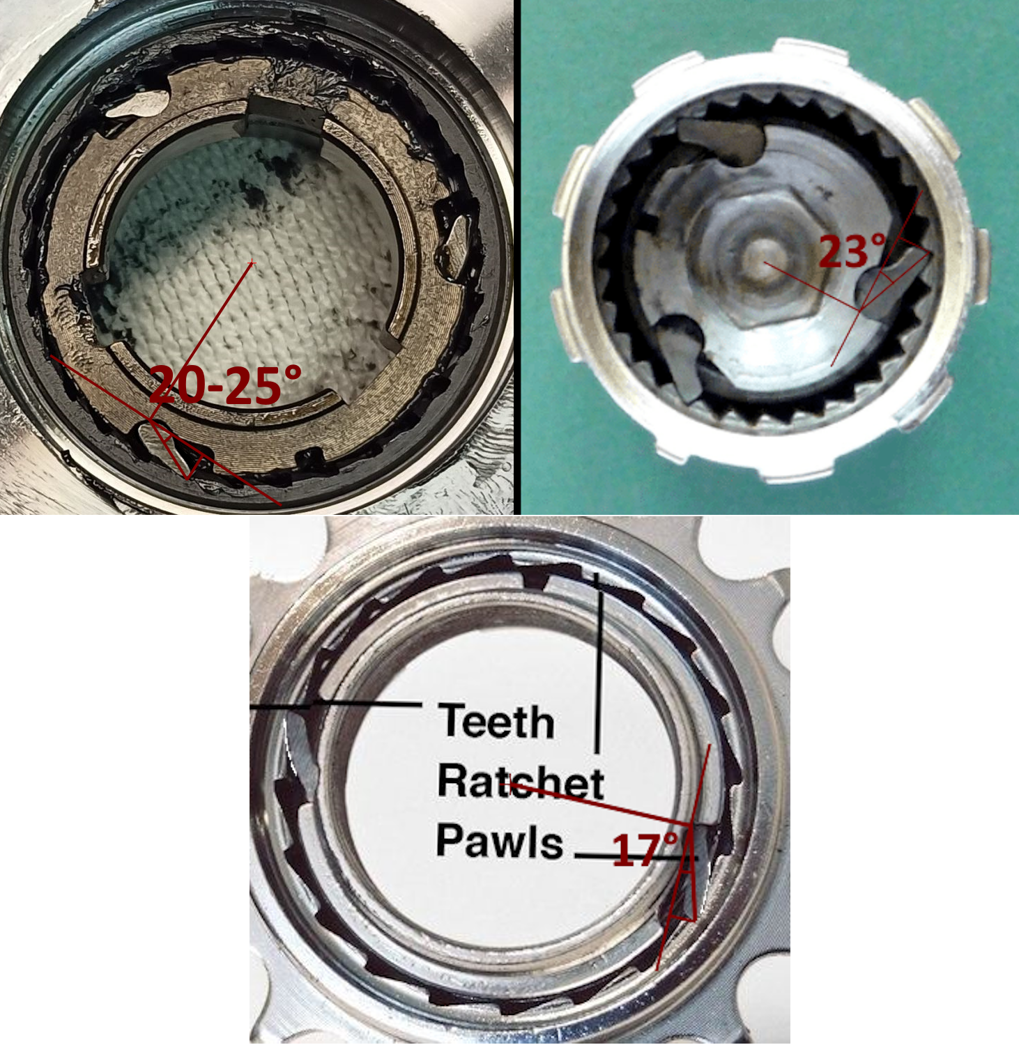
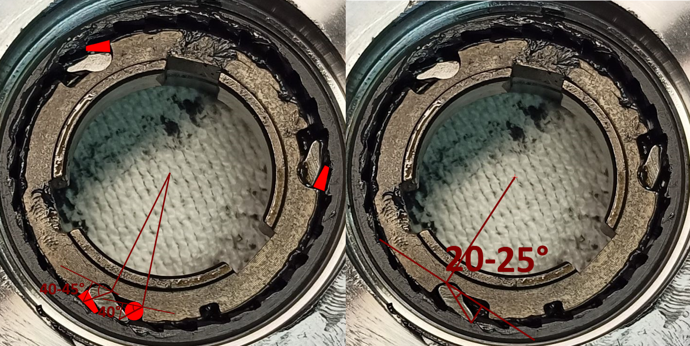
You're right that a roller clutch exerts high radial forces on the assembly, necessary, because when locked, it is relying on friction between smooth metal parts, and it would be designed for those loads. Ratchets do not exert nearly the same radial loads; If you draw a line tangent to the diameter at the pawl pivot points, then join that with the angle of the pawls when locked, and a third line perpindicular to that first tangent line, you have a right triangle which describes the forces involved; Let us say the pawl angle is 30 degrees, probably less, but that's a good worst case, when engaged with the tooth, the "adjacent" side (across from the hypotenuse/pawl-line), is your circumferential driving force, which is (pawl compression load)cos(30 deg) = 0.87 or 87% of the pawl compression load, pretty good. The radial load is the "opposite" side to the 30 degree angle, so (pawl compression load)sin(30 deg) = 0.5 or 50% of the pawl load, so-so, making the pawl locked angle as 20 degrees will cut that down to 34%, better. 10 degree pawls provides 17% radial and 98% drive loads, now we're talking.
With a roller clutch, it's the opposite in concept; A higher wedge angle will exert less radial load, but may slip. A lower wedge angle is more likely to generate sufficient friction to lock, but at the expense of higher outward radial load, so those inner and outer rings need to be stronger and stiffer (two distinctly different properties, by the way) than with a ratchet. That is the advantage of a ratchet, the assembly can be lighter and manage the loads, at the expense of clicking sound when overunning, and needing strong and hard pawls, pivot pins, and teeth, and very durable pawl springs which are tiny but may go through millions of cycles in the life of the hub.
With a roller clutch, it's the opposite in concept; A higher wedge angle will exert less radial load, but may slip. A lower wedge angle is more likely to generate sufficient friction to lock, but at the expense of higher outward radial load, so those inner and outer rings need to be stronger and stiffer (two distinctly different properties, by the way) than with a ratchet. That is the advantage of a ratchet, the assembly can be lighter and manage the loads, at the expense of clicking sound when overunning, and needing strong and hard pawls, pivot pins, and teeth, and very durable pawl springs which are tiny but may go through millions of cycles in the life of the hub.
Thank you for explaining. That�s very interesting, it�s not where I thought it would eat the most into the margins, certainly not exceeding them. It would for sure reduce the maximum design loads though. Keep in mind that the load in that direction won�t be nearly as much, as it is to activate a coaster brake by back-pedaling.
To make sure I understood, and make skimming through this thread for other people easier, here are some illustrations of the issue you raised :
Btw if you don't mind, what are the freewheel�s �pivots pins� you mentioned?
Trying to lock the pawls outward is even worse than a roller clutch; The rollers are solid and hard so difficult to compress; The pawls, at a shallow angle and the ratchet run backwards, the compression force trying to push the pawls in is great; Possibly something solid steel and very hard and high strength metal (like a roller or ball bearing) behind the pawl might stand up to the load, however, a steel ball or pin behind the ratchet will be pushing on the center of the pawl, and the unsupported end of the pawl will probably snap off, as well as the outer ratchet ring, under outward radial loads well above design, may "burst" circumferentially, as its hardness will probably prevent much plastic stretching before ultimate tensile failure.
Two coaxial opposed ratchets could work. However, bike hub ratchets are designed for human drive loads. If you have a motor that exceeds that load, or, under hard braking you exert greater torque on the ratchet than normal human power, it may overload whichever ratchet is handling braking.
Let's see... did I forget any of your questions? I think that will do for now.
Like I said, I don't understand exactly your intended implementation for the locked hub, if I recall, I think you may have said a motor is involved. But I hope the above helps.
Let's see... did I forget any of your questions? I think that will do for now.
Like I said, I don't understand exactly your intended implementation for the locked hub, if I recall, I think you may have said a motor is involved. But I hope the above helps.
That said, on the previous motor version, this pawl freewheel was a sprag-clutch, same as the one taking the motor torque. Well apparently, it was mostly the �normal human power� activated sprag clutch that would fail, not the one under the motor torque. The motor torque may easily introduce more fatigue over time, but the issue with the freewheel taking the load of the cranks is that it�s not only taking the normal working load of your pedaling, but also all the impacts, bumps and misuse.
Yes, you answered all of it and that was a lot, thank you again for you help.
Even at a low temperature though, as the freewheel is press fit in the rest of the main gear, I would not feel confident to heat up the whole thing without first extracting the freewheel, at which point I might be better off trying to replace it with a bushing.
If I can�t manage to procure/make a bushing though, you�re right, I should braze/solder it with the lowest temperature that keeps the hardened steel properties. I should also find the stronger solder alloy possible, under that temperature, though.
 04-03-24, 01:34 AM
#27
Senior Member
(post above) Superb illustrations! Yes, that's exactly the angle I was talking about, in each case.
Pivot pins: Sorry, I was thinking of my old 3-speed hub, the pawls had a hole through them and they rode on a pivot pin with a tiny pawl spring holding each pawl in engagement with the toothed ring. Your pawls have no pivot pin.
Ratchet failure load: Gosh I have no idea. Those pawls are at an excellent angle to transmit torque with minimal outward radial force. They are also short for their width so less likely to buckle. Everything is hardened steel so not much malleability, steel is fantastically strong when loaded in compression, so I don't know if the pawls will collapse, or their pivot root, or the ratchet ring. Looking at the thickness of the inner and outer rings, I think the pawl would fail first, probably the thin end of each failing in compression.
Last edited by Duragrouch; 04-03-24 at 01:41 AM.

