


My E+ review
 07-23-20, 05:09 PM
#626
Senior Member
Join Date: Aug 2011
Location: Western Canada
Posts: 689
Bikes: E+ kit, BIONX
Mentioned: 5 Post(s)
Tagged: 0 Thread(s)
Quoted: 58 Post(s)
Likes: 0
Liked 10 Times
in
7 Posts
beauty of EPLUS drive is that I can descent very steep downhill part of pathway with my hands not touching any brake levers.
in regen level 9 .
putting EPLUS on the bicycle exercise stand during winter times and exercising with variable regen is wonderful feature, no any mechanical adjustment like in traditional exercise machines.
pressing brake lever on EPLUS closes regen curcuit with fixed force which is determined by back EMF force of motor and this is established by software as far as I know.
 08-26-20, 07:30 PM
#627
Junior Member
Join Date: Jul 2011
Posts: 96
Mentioned: 0 Post(s)
Tagged: 0 Thread(s)
Quoted: 9 Post(s)
Likes: 0
Liked 5 Times
in
5 Posts
LiPo BMS board
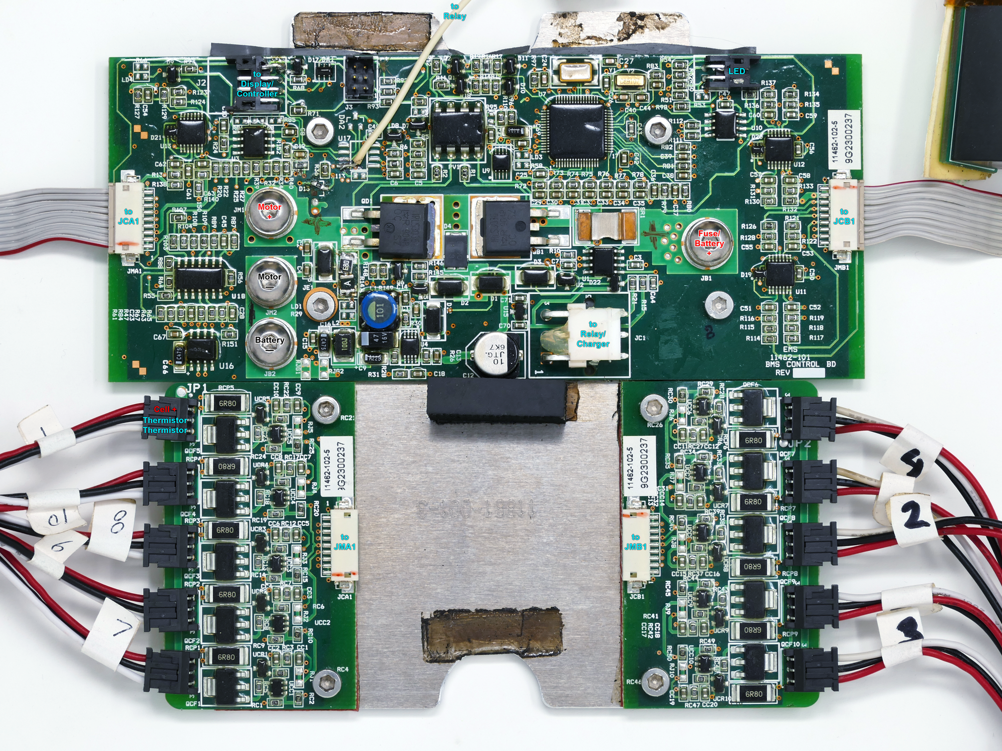
Back in post 210, Powell showed how he is using a couple of the NiMH battery sense boards with lithium button cells to get the BMS board to work with his lithium conversion. I had overlooked this detail when I tested an E+ LiPo BMS board that I am trying to salvage, and I think that is why the test failed. I would like to try the same trick with proxy batteries, but the cell sensing setup is a bit different. There was a lead connected to the positive terminal of each cell, but unlike the hub BMS, there are no individual negative connections. They are the ten connectors in the bottom half of the photo below.
E+ LiPo BMS board
Since I know only enough electronics to be dangerous, and actually understand less, I'm hoping someone may recognize this kind of BMS configuration and be able to offer a more informed opinion on this question: Is it reasonable to assume that one could fool the BMS into thinking the original batteries were present and in good health by connecting the positive of a ~3.7V power source to one of the sense terminals, and the negative of the same power source to the negative 36V side of the whole system?
08-27-20, 09:06 AM
#628
Senior Member
Join Date: Aug 2011
Location: Western Canada
Posts: 689
Bikes: E+ kit, BIONX
Mentioned: 5 Post(s)
Tagged: 0 Thread(s)
Quoted: 58 Post(s)
Likes: 0
Liked 10 Times
in
7 Posts
Wrandyr
to start with ,
can you tell us what was original configuration of LiPolymer EPLUS battery?
series, paraller
I presume 10S1P configuaration.I
to start with ,
can you tell us what was original configuration of LiPolymer EPLUS battery?
series, paraller
I presume 10S1P configuaration.I
08-27-20, 03:40 PM
#630
Senior Member
Join Date: Aug 2011
Location: Western Canada
Posts: 689
Bikes: E+ kit, BIONX
Mentioned: 5 Post(s)
Tagged: 0 Thread(s)
Quoted: 58 Post(s)
Likes: 0
Liked 10 Times
in
7 Posts
very fine of piece of electronic engineering which failed big time.
so 10S , typical Lithium cell is 4.2V fully charged, times 10 = 42V - ideal for EPLUS.
I power my EPLUS on 11S but I dont charge fully.
to start with this BMS worked with EPLUS system, so on power up disp/contr. made hand shake with this BMS /on disp/contr. you have battA and battB to chose from.
my battery pack for EPLUS does not use any BMS , no any kind of balancing, I am anti-BMS person.
Chevy Volt cells I used for building my pack stay balanced . I am reluctant to risk cells life and possibly fire with BMS electronics.
I THINK using this EPLUS BMS without all EPLUS system does not make sense to me.
AGAIN:
As you probably know beginning of the end of EMS COMPANY /Eplus manufacturer/ was a Eplus batteryB fire in one of bike shops in USA.
battery B controlled by this BMS.
and why this sophiticated piece of electronics did not prevent overcharge**********
Last edited by powell; 09-02-20 at 05:19 AM.
09-25-20, 05:11 PM
#631
Senior Member
Join Date: Aug 2011
Location: Western Canada
Posts: 689
Bikes: E+ kit, BIONX
Mentioned: 5 Post(s)
Tagged: 0 Thread(s)
Quoted: 58 Post(s)
Likes: 0
Liked 10 Times
in
7 Posts
Another milestone in my EPLUS history.
today my EPLUS equipped BIRIA reached over 40,000 kilometers millage !!!
again
it is same EPLUS drive/motor used with 3 different batteries over years of usage.
of course my EPLUS has some problems over so many kilometers of use.
knowledge and skills are the key to keeping any ebike to run, EPLUS also.
but far the biggest problem of original EPLUS was display/controller switches.
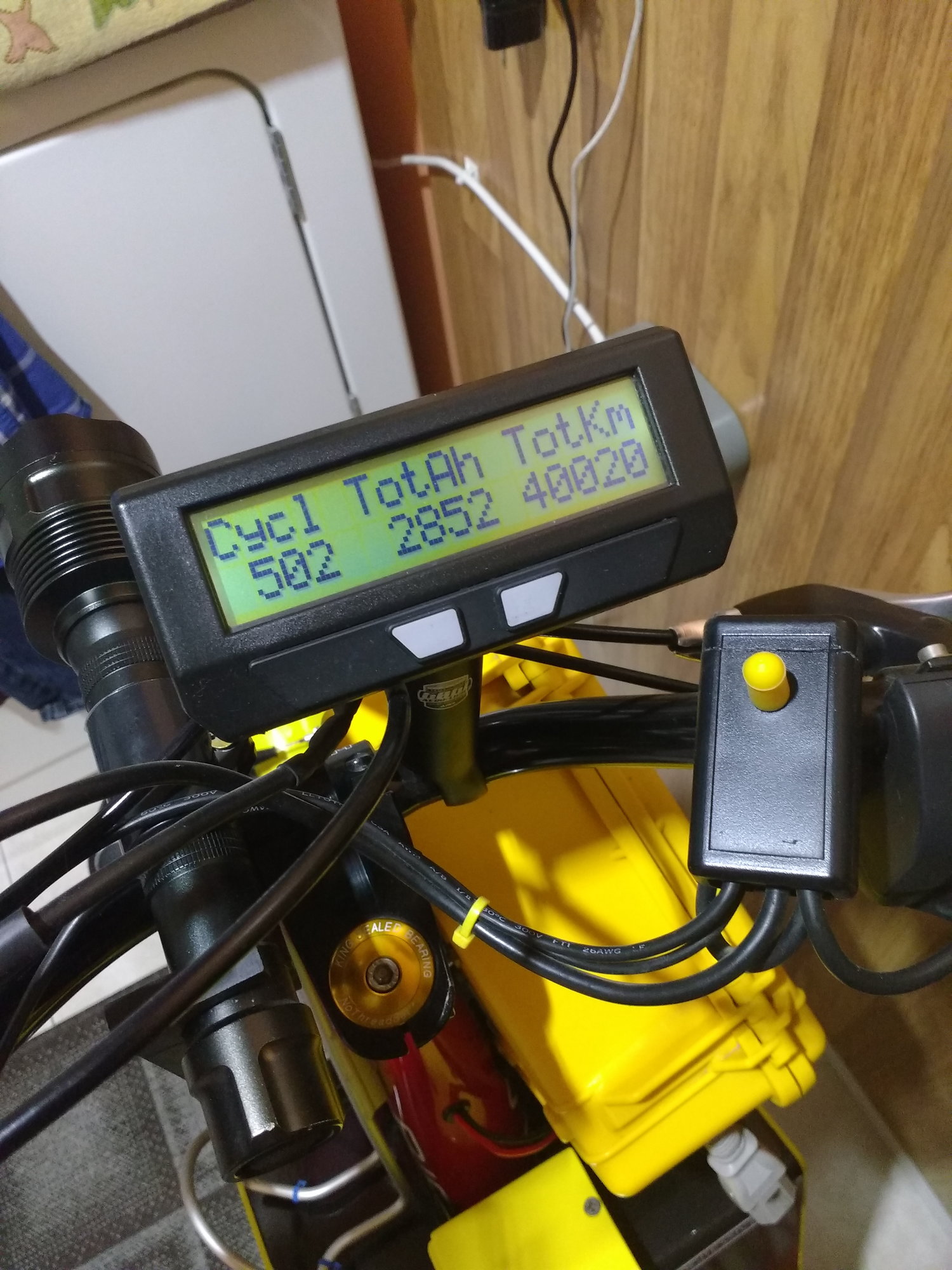
Cycle Analyst does not lie 40,000 km
today my EPLUS equipped BIRIA reached over 40,000 kilometers millage !!!
again
it is same EPLUS drive/motor used with 3 different batteries over years of usage.
of course my EPLUS has some problems over so many kilometers of use.
knowledge and skills are the key to keeping any ebike to run, EPLUS also.
but far the biggest problem of original EPLUS was display/controller switches.
Cycle Analyst does not lie 40,000 km
Last edited by powell; 09-25-20 at 05:18 PM. Reason: more ifo
09-27-20, 09:53 PM
#633
Junior Member
Join Date: Jul 2011
Posts: 96
Mentioned: 0 Post(s)
Tagged: 0 Thread(s)
Quoted: 9 Post(s)
Likes: 0
Liked 5 Times
in
5 Posts
@ Firedog: The E+ LiPo system did not allow regen braking at all. The cable from the display to the battery board in it has the contact for pin 8 pulled from the connector housing and folded back. I suspect that they were using the same wiring harness for both types of batteries, and this is what disables regen.
09-29-20, 05:08 PM
#634
Senior Member
Join Date: Aug 2011
Location: Western Canada
Posts: 689
Bikes: E+ kit, BIONX
Mentioned: 5 Post(s)
Tagged: 0 Thread(s)
Quoted: 58 Post(s)
Likes: 0
Liked 10 Times
in
7 Posts
Wrandyr.
I was rather blunt and harsh writing about this EPLUS battB electronics.
sorry for this,
I understand you, you want to put such nice looking board to use.
but it does not change fact that that board controlled LiPolymer cells which caught fire.
of course balancing conditions of cells , LVC, HVC voltages are determined by software loaded on the processor you can see .
thank you for congratulations
yellow is a toggle switch , as you can see I have two throttles in paraller switched by this toggle switch.
why 2 throttles?
one for lower handlebars ,second for high riding position with bar ends.
10-10-20, 07:42 PM
#637
Junior Member
Join Date: Jul 2011
Posts: 96
Mentioned: 0 Post(s)
Tagged: 0 Thread(s)
Quoted: 9 Post(s)
Likes: 0
Liked 5 Times
in
5 Posts
@powell,
You may have misunderstood my intent. I'm not proposing to rebuild my LiPo battery with new cells. Rather, I want to try to use it with power tool battery packs in the same way that you have shown us how to use other batteries with the hub controller. You had a couple of coin cells rigged up with the battery pack boards to spoof the controller into thinking the original batteries were present. The boards have positive and negative connections, so splicing in the coin cells is pretty straightforward. The LiPo controller only has a a positive connection between each cell. Having nothing to lose, I decided to try connecting 3.7V lithium coin cells to the controller. One or two didn't work, so I tried ten, as the original battery had ten cells. The good news is that it appears to work. The display lights up, it appears as the B battery, and the motor runs. My test rig is too delicate to ride, so I haven't done that. As others have noted, the SoC display is not accurate. It shows one bar. My question for those with conversion experience is will it stay at one bar indefinitely? If if eventually drops to LVCO, there doesn't seem to be any way to recover, and the system would be useless.
The bad news is that I also was trying to convert one of my hub controllers to an alternate battery, and I seem to have done something that killed it.
10-14-20, 06:46 PM
#638
Senior Member
Join Date: Aug 2011
Location: Western Canada
Posts: 689
Bikes: E+ kit, BIONX
Mentioned: 5 Post(s)
Tagged: 0 Thread(s)
Quoted: 58 Post(s)
Likes: 0
Liked 10 Times
in
7 Posts
Wrandyr
since your purpose /as you write above/
is to use this battB board with power tool battery packs, right?
so I am going to write only about this.
what power tools packs, what configuration, how many packs???
please
consider that every tool pack has his own electronics which monitor cells voltages, temp, LVC, HVC, etc.
now you want to use batB board to this power tool packs cells?
paraller to power tool pack electronics?
to me
you should have either factory power pack electronics OR
EPLUS battB electronics, no two at the same time.
10-16-20, 06:35 PM
#639
Junior Member
Join Date: Jul 2011
Posts: 96
Mentioned: 0 Post(s)
Tagged: 0 Thread(s)
Quoted: 9 Post(s)
Likes: 0
Liked 5 Times
in
5 Posts
Yes, power tool batteries only. I am testing with two Milwaukee 18V 8AH batteries in series, connected only to the + and - battery terminals.
12-11-20, 11:57 PM
#642
Senior Member
12-28-20, 08:00 AM
#644
Full Member
Thread Starter
Join Date: Nov 2008
Posts: 355
Mentioned: 0 Post(s)
Tagged: 0 Thread(s)
Quoted: 10 Post(s)
Likes: 0
Liked 3 Times
in
3 Posts
I listed my two E Plus chargers on ebay if anybody is looking for one.
EPLUS E+ E PLUS ELECTRIC BIKE BATTERY CHARGER $50 SHIPPED | eBay
EPLUS E+ E PLUS ELECTRIC BIKE BATTERY CHARGER $50 SHIPPED | eBay
01-29-21, 09:15 PM
#645
Senior Member
Join Date: Aug 2012
Location: San Diego
Posts: 51
Bikes: Univega Superstrada, Serrota, Santana tandem, E plus
Mentioned: 0 Post(s)
Tagged: 0 Thread(s)
Quoted: 18 Post(s)
Likes: 0
Liked 8 Times
in
8 Posts
More errors. I've finally given up on E+'s electronics and gutted it.
I struggled with my E+ bike for 6 years. When it worked, nothing can compare with it's power and features. Much too often, unexplained, untraceable errors crop up. I can't trust it to ride or sell.
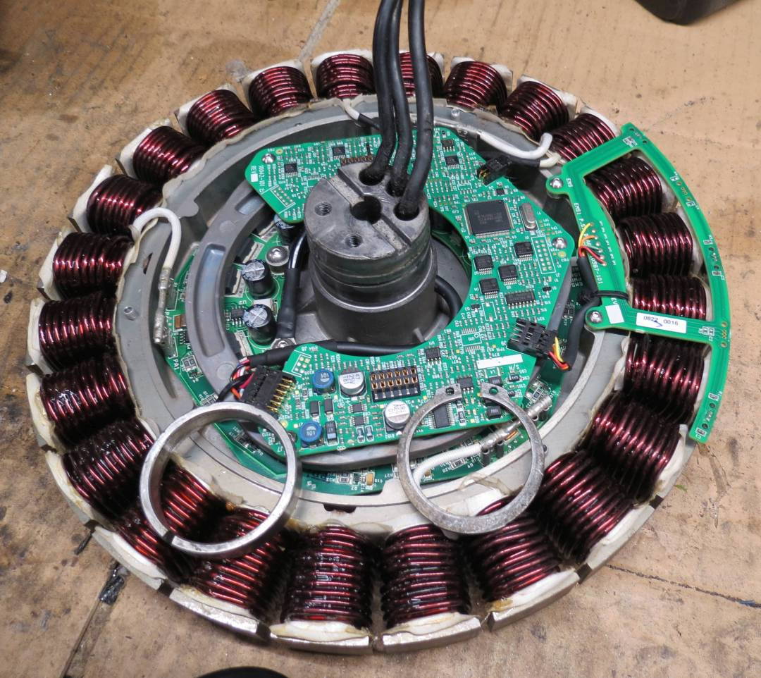
The rear hub motor has the controller built inside a powerful and very well constructed 3 phase brushless direct hub motor with 3 hall sensor. Bypass the controller (get rid of it), bring the 3 phase wire and 5 hall sensor wires out to a new, reliable, documented controller was my final solution.
Opening the motor to access to the halls and phase wires isn't easy. A collar is pressed on to the axle that must be first removed in order to access and release a cir-clip and open the motor. Trying to remove it, I stripped gear pullers even after heating the collar with a micro torch. Finally, I cut the collar with a cutoff blade on a hand held grinder. The collar's purpose is to keep the square pins connecting the torque arm to the axle in place. I think the collar, even cut, will still do that job after gluing the collar back in place with JB weld.
Once access is gained, it a simple matter to remove the 2 controller circuit board and the original power and control wires that pass through the axle. 3 heavy phase wires and the 5 hall sensor wire easily pass through 2 of the 3 holes and get soldered directly to the motor.
I bench tested it with both a 17a and 35a controller. Motor is smooth and quiet. I can now test several controllers at various voltages (36, 54, ?v) to find a performance, features and efficiency that suits my riding style.
Likes For Firedog91902:
01-31-21, 10:25 PM
#646
Newbie
Join Date: Nov 2010
Location: S.CA (91763)
Posts: 53
Bikes: 18 Tidalforce (+3 M750 E+) ebikes, 27 EVG ebikes, 2 Blk '13 A2B Shima, 1 UM '10 Velociti 26", 2 UM Europa's, 2 eZip trail, 1 iZip 24v Urban, 1 eZip 1000 scooter, 1 Chinese 48v ped-scooter
Mentioned: 0 Post(s)
Tagged: 0 Thread(s)
Quoted: 17 Post(s)
Liked 0 Times
in
0 Posts
Got E+?
Ok.....it appears that this last adventure might be the way to go with "dead" E+'s, vs taking out the front battery board, and then adding an outside battery source!
I've got 3 "dead" E+'s, so I'll be watching and seeing what controller & battery voltage you decide on. :-)
I've got 3 "dead" E+'s, so I'll be watching and seeing what controller & battery voltage you decide on. :-)
Last edited by kauaikit; 01-31-21 at 10:29 PM.
02-01-21, 12:21 AM
#647
Senior Member
Join Date: Aug 2012
Location: San Diego
Posts: 51
Bikes: Univega Superstrada, Serrota, Santana tandem, E plus
Mentioned: 0 Post(s)
Tagged: 0 Thread(s)
Quoted: 18 Post(s)
Likes: 0
Liked 8 Times
in
8 Posts
Gutted E+ hub motor- Interesting controller results
I tested several controllers on the E+ motor connecting directly to its hall sensors and 3 phase wires. My "go to" controller is a 36/48v 350w which I run at 54V (3x18v). It delivers 17-18amps (~1000w) with no problems on every geared and direct hub motor I've tried . Same set up with the gutted E+ but the maximum current is only 11-12 amps. Tried 54V with a 48/64v 35a controller; maybe got 13a max. WTF? My tester shows nothing unusual with the motor or hall sensors;.60 degrees phase. These controllers have a learning mode which sets up the best optimal setting for any motor connected. The "learning" was normal. Could the phase coils of the E+ have a much higher resistance than others? I'd appreciated any ideas. I'll ask the question at Endless Sphere. There are some real technical experts over there that may have an idea.
https://endless-sphere.com/forums/vi...p?f=2&t=110242
I had hope to duplicate or exceed the performance and top speed of the original E+. I expected to need a 1500W at 54v, but that ain't going to work.
I'm still glad I gave up on E+ electronics. The gutted motor and a $10 controller will make a nice, reliable ride for someone that's happy with 20-22mph. It will probably last forever.
Last edited by Firedog91902; 02-01-21 at 08:22 PM.
Likes For Firedog91902:
02-06-21, 12:08 PM
#650
Senior Member
Join Date: Aug 2011
Location: Western Canada
Posts: 689
Bikes: E+ kit, BIONX
Mentioned: 5 Post(s)
Tagged: 0 Thread(s)
Quoted: 58 Post(s)
Likes: 0
Liked 10 Times
in
7 Posts
Firedog,
I read your posts carefully about power tool batteries you used with your Eplus.
you obviously change my schematics of conversion to non-Eplus battery.
You obviously forgot about electronics BMS inside power tool packs,
no wonder your Eplus acted like you described.
and to blame EPLUS???
my conversion schematics is simple as hell , you connect 10 or 11 cells in series to Eplus power board NOTHING MORE,
but
you connected power tool packs electronics to my conversion scheme and you expect no problems?
You must first understand what happens when these power tool BMS interfere with upper Eplus BMS board /called processing board or control board/
especially if you tap into two cells to connect to processing upper board
you add such complexity to all conversion schematics.
again
my conversion schematics shows only 11, 12 cells in series connected terminals of Eplus power board.
again
BMS electronics inside power tool pack monitors every cell during charging and discharging, they cannot disconnect wires going to individual cells EXCEPT openning pack and cutting wires. If you want to use power tool pack you must disconnect electronics inside.
outside pins/connectors does not allow to isolate cells from electronics
Last edited by powell; 02-07-21 at 08:01 AM.