


Mafac "Racer" off-centre-pull
 04-09-22, 02:12 PM
#26

Senior Member

Join Date: Feb 2017
Location: Northern Shenandoah Valley
Posts: 4,176
Bikes: More bikes than riders
Liked 801 Times
in
591 Posts
I haven't seen as much information on setting straddle wire height for Racers as I have for cantilevers. Does one typically want the straddle wire to intersect the brake arm at about a right (90 degree) angle to the pivot? In other words, draw a straight line between each arm's cable attachment point and the pivot (line AP)...and then draw a line from that from the attachment point up towards the straddle wire hanger (line AH). Should that included angle be about 90 degrees?
I imagine if you set the straddle wire too low (the included angle is less than 90 degrees), some of your pulling force will be directed toward the pivot itself, and the arm would move with more speed and less force (less mechanical advantage)? Then, as you pull the arm further, the speed would slow and you'd get more mechanical advantage as the included angle approaches 90 degrees. Is that about right? Or totally off?
I imagine if you set the straddle wire too low (the included angle is less than 90 degrees), some of your pulling force will be directed toward the pivot itself, and the arm would move with more speed and less force (less mechanical advantage)? Then, as you pull the arm further, the speed would slow and you'd get more mechanical advantage as the included angle approaches 90 degrees. Is that about right? Or totally off?
 04-09-22, 03:46 PM
#27
Senior Member
Join Date: Apr 2011
Location: Maryland, USA
Posts: 2,657
Bikes: Drysdale/Gitane/Zeus/Masi/Falcon/Palo Alto/Raleigh/Legnano
Liked 757 Times
in
463 Posts
Amir Avitzur has several Flickr albums that are extremely useful for researching all things MAFAC.
MAFAC Top 63///Here's the MAFAC Tiger you mentioned:///I couldn't find a Competition model with the ball joints.
MAFAC Top 63///Here's the MAFAC Tiger you mentioned:///I couldn't find a Competition model with the ball joints.
(a) Yeah, no Competition with ball and socket,
(b) you'd think a product called "Tiger" would be permanently etched in my mind, and this is the first I'd heard of it,
(c) looking at the B&S attachment, I'd see it's fine for alignment up and down but not for toe-in, so why design it that way?
(d) no idea on reach so perhaps not useful to the OP
(e) now I need to locate a set of Tiger brakes just due to the name?

__________________
Larry:1958 Drysdale, 1961 Gitane Gran Sport, 1974 Zeus track, 1988 Masi Gran Corsa, 1974 Falcon, 1980 Palo Alto, 1973 Raleigh Gran Sport, 1974 Legnano. Susan: 1976 Windsor Profesional.
Larry:1958 Drysdale, 1961 Gitane Gran Sport, 1974 Zeus track, 1988 Masi Gran Corsa, 1974 Falcon, 1980 Palo Alto, 1973 Raleigh Gran Sport, 1974 Legnano. Susan: 1976 Windsor Profesional.
04-09-22, 04:54 PM
#28
Senior Member
04-09-22, 07:22 PM
#29
Senior Member
I have a pair of MAFAC "Racer" center pulls that were "harvested" from an older Peugeot and are destined for a bit newer Peugeot "custom" (but entry level) build up. I definitely concur with the mention that the red plastic spacers are likely to be somewhat brittle and one needs to be very careful in the disassembly process so as NOT to damage them. The suggestion that the straddle cable and yoke interface be free of kinks (in the former) and free of corrosion (in the latter) is important. Another potential issue is corrosion on the arm of the spring that "pushes" the caliper out (and the pad away from the rim)! It needs to be able to slide in the notch of the little nipple on the back side of the caliper arm. Friction at that interface "may" prevent the self-centering of the caliper. Movement at this interface may be miniscule but could add to the problem. Friction at the caliper arm pivots is prolly most critical but the other areas may have impact also. If the assembly is to be taken apart, one might as well ensure that friction at every interface is minimized. Just sayin' !
04-09-22, 07:41 PM
#30
Senior Member
Join Date: Oct 2014
Location: Portland, OR
Posts: 13,336
Bikes: (2) ti TiCycles, 2007 w/ triple and 2011 fixed, 1979 Peter Mooney, ~1983 Trek 420 now fixed and ~1973 Raleigh Carlton Competition gravel grinder
Liked 4,339 Times
in
2,793 Posts
Likes For 79pmooney:
04-10-22, 01:45 AM
#31
Full Member
Thread Starter
Well, this is interesting. My problem turns out to have nothing to do with the straddle cable. When I take off the straddle cable (from one side, anyway), remove the nut and curious contoured giant washer from the back, pull the brake out the front, hold it in my hand from one brake shoe to the other -- like a curiously uncomfortable version of
-- and squeeze, the result is utterly asymmetrical. The arm for the left brake shoe pivots as it should; the arm for the right one doesn't seem to pivot at all. For what little looking at the non-disassembled brake is worth, nothing seems amiss. As for disassembling it, of course I'd want to do that on a table rather than with it kind-of resting on the front tyre. Both wires are cut short and soldered: if I cut off the soldered section the result might be hard to re-thread. I could sacrifice the brake cable, or I could try to unhook the straddle cable from the, uh
without removing the brake cable from the latter: I'd guess that this would be possible but that reversing the procedure would not. So I think that I'll limp to LFBS (local frame-builder shop) and ask him (the last time we talked, before there was any trouble with the brake or indeed anything else, he seemed keen to give the bike a look-over), and if he's not keen to look into the brake I'll buy a spare brake cable or two (always good to have around) and take a look myself.
Unfortunately for me, your area of the Pacific rim and mine have very different pricing. Though a couple of years ago I did pick up a very spiffy example of a Shimano 600 centre-pull brake, because it was $10 or so (probably because it had lost its twin) and I had a vague feeling that it might be useful some day.
-- and squeeze, the result is utterly asymmetrical. The arm for the left brake shoe pivots as it should; the arm for the right one doesn't seem to pivot at all. For what little looking at the non-disassembled brake is worth, nothing seems amiss. As for disassembling it, of course I'd want to do that on a table rather than with it kind-of resting on the front tyre. Both wires are cut short and soldered: if I cut off the soldered section the result might be hard to re-thread. I could sacrifice the brake cable, or I could try to unhook the straddle cable from the, uh
without removing the brake cable from the latter: I'd guess that this would be possible but that reversing the procedure would not. So I think that I'll limp to LFBS (local frame-builder shop) and ask him (the last time we talked, before there was any trouble with the brake or indeed anything else, he seemed keen to give the bike a look-over), and if he's not keen to look into the brake I'll buy a spare brake cable or two (always good to have around) and take a look myself.
Hmm, I just bought a lot of 4 sets complete for $80. Racers can be found for cheap.
04-10-22, 04:11 AM
#33
-- and squeeze, the result is utterly asymmetrical. The arm for the left brake shoe pivots as it should; the arm for the right one doesn't seem to pivot at all. For what little looking at the non-disassembled brake is worth, nothing seems amiss. As for disassembling it, of course I'd want to do that on a table rather than with it kind-of resting on the front tyre. Both wires are cut short and soldered: if I cut off the soldered section the result might be hard to re-thread. I could sacrifice the brake cable, or I could try to unhook the straddle cable from the, uh
without removing the brake cable from the latter: I'd guess that this would be possible but that reversing the procedure would not.
One of the pivots doesn't.
You need to undo the screw that holds that arm on. This can be done on the bike; depending on what tool you use you may want to remove the wheel to get access.
One of the best tools for this is one of those flat steel stamped multi-size ones. The flats are very thin, so sockets are NOT good *unless* you grind the ends flat. You want a good-fitting tool especially if you also know the pivot's stuck - the screw may have some corrosion.
Unhook the straddle cable and as mentioned above release the spring. Undo the screw, remove the arm (here you can determine how bad the pivot is by how hard you have to wiggle it to get it off), lubricate it and re-assemble.
Then do the other one, you need the practice.
04-10-22, 04:54 AM
#34
Full Member
Thread Starter
04-10-22, 06:57 AM
#35
Bike Butcher of Portland

Join Date: Jul 2014
Location: Portland, OR
Posts: 11,806
Bikes: It's complicated.
Liked 6,174 Times
in
2,402 Posts
MAFAC centerpulls are made to disassemble easily.
As [MENTION=512318]oneclick[/MENTION] mentions, this is readily done on the bike.
Before you start to do any disassembly, disconnect the springs first, this will make disassembly much easier.
Here's a blow up diagram of a MAFAC Racer.
As [MENTION=512318]oneclick[/MENTION] mentions, this is readily done on the bike.
Before you start to do any disassembly, disconnect the springs first, this will make disassembly much easier.
Here's a blow up diagram of a MAFAC Racer.
__________________
If someone tells you that you have enough bicycles and you don't need any more, stop talking to them. You don't need that kind of negativity in your life.
If someone tells you that you have enough bicycles and you don't need any more, stop talking to them. You don't need that kind of negativity in your life.
04-10-22, 08:20 AM
#36
Senior Member
Join Date: Jun 2021
Posts: 1,790
Bikes: '38 Schwinn New World, ’69 Peugeot PX-10, '72 Peugeot PX-10, ‘7? Valgan, '78 Raleigh Comp GS, ’79 Holdsworth Pro, ’80 Peugeot TH-8 tandem, '87 Trek 400T, ‘7? Raleigh Sports, ‘7? Raleigh Superbe, ‘6? Hercules
Liked 1,712 Times
in
816 Posts
As for disassembling it, of course I'd want to do that on a table rather than with it kind-of resting on the front tyre. Both wires are cut short and soldered: if I cut off the soldered section the result might be hard to re-thread. I could sacrifice the brake cable, or I could try to unhook the straddle cable from the, uh
without removing the brake cable from the latter: I'd guess that this would be possible but that reversing the procedure would not. So I think that I'll limp to LFBS (local frame-builder shop) and ask him (the last time we talked, before there was any trouble with the brake or indeed anything else, he seemed keen to give the bike a look-over), and if he's not keen to look into the brake I'll buy a spare brake cable or two (always good to have around) and take a look myself.
without removing the brake cable from the latter: I'd guess that this would be possible but that reversing the procedure would not. So I think that I'll limp to LFBS (local frame-builder shop) and ask him (the last time we talked, before there was any trouble with the brake or indeed anything else, he seemed keen to give the bike a look-over), and if he's not keen to look into the brake I'll buy a spare brake cable or two (always good to have around) and take a look myself.
04-10-22, 10:04 AM
#37
Full Member

Amazing. Here I am, discovering new dimensions of my own ignorance. One thing I thought I did know was never to use one of those tools, unless of course one was on the road and there was nothing better at hand, And that's one reason why I don't have one. I do have a 12mm what-I-thought-was-a-cone-spanner; when I read Sheldon Brown on the matter, I realize that what I have is intermediate between a cone wrench/spanner and a regular wrench/spanner. I'll try it tomorrow morning, carefully.
04-14-22, 09:15 AM
#38

Senior Member

For reference.


04-14-22, 01:20 PM
#39
Senior Member

Join Date: May 2020
Location: Great White North
Posts: 1,249
Bikes: 2013 Cannondale Caad 8, 2010 Opus Fidelio, 1985 Peugeot UO14, 1999 Peugeot Dune, Sakai Select, L'Avantage, 1999 Specialized Hard Rock
Liked 498 Times
in
309 Posts
On the subject of Mafac Racers, what's the solution for replacing the brake pads? Are there specific pads you would buy or can you get mountain bike brake pads that would work?
04-14-22, 04:57 PM
#40
Senior Member
Koolstop makes replacements that fit perfectly�Available in both black and salmon compounds. I prefer the black for both appearance and performance, but people who ride in the rain a lot seem to prefer the salmon. Replacing the original pads with these should be the first step in living with a bike with Mafacs that gets ridden.
Likes For El Chaba:
04-14-22, 05:08 PM
#41
Senior Member
Koolstop makes replacements that fit perfectly�Available in both black and salmon compounds. I prefer the black for both appearance and performance, but people who ride in the rain a lot seem to prefer the salmon. Replacing the original pads with these should be the first step in living with a bike with Mafacs that gets ridden.


Likes For markk900:
04-17-22, 08:19 PM
#42
Full Member
Thread Starter
Friends don't let are hesitant about recommending that friends buy from immense oligopolists named after rivers, but the last time I looked Amazon Japan (where I happen to be) was selling Koolstop pads for Mafac shoes: black for a palatable price; salmon for an impalatable one.
OP speaking. I was suddenly hit with a pile of (salaried) work, so I had to hold back for a couple of days; but I have looked at my front Mafac "Racer". If I may steal gugie 's photo (and demonstrate my utter incompetence with Gimp):
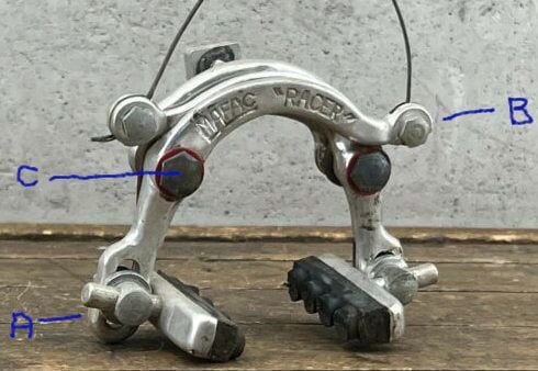
After unhooking the straddle cable and dislodging the lower end of each of the two springs, I undid bolt "C". It came out very smoothly and is in excellent condition. I assumed that the outermost plate (the one stamped 'MAFAC "RACER"') would come off easily. However, it won't. It won't even start to come off.
When anything's stuck, I reach for the can of WD-40. (I don't know any better.) I liberally sprayed it onto any relevant-looking bits and left the brake for a couple of days.
My hands aren't particularly strong. OK, they're weak. Pushing and pulling on "A" doesn't trigger any pivoting around "C" Neither does pushing and pulling on "B". But with "A" between one thumb and forefinger and "B" between the other thumb and forefinger, I can get it to pivot, reluctantly. (There's far too much friction.)
If I used inserted the business end of a wide-bladed T-handle screwdriver under the "M" of "MAFAC" and twisted, this might move the plate off. Or it might just deform or break something (but not the screwdriver). No, it seems a stupid approach. But what's a more intelligent approach?
OP speaking. I was suddenly hit with a pile of (salaried) work, so I had to hold back for a couple of days; but I have looked at my front Mafac "Racer". If I may steal gugie 's photo (and demonstrate my utter incompetence with Gimp):
After unhooking the straddle cable and dislodging the lower end of each of the two springs, I undid bolt "C". It came out very smoothly and is in excellent condition. I assumed that the outermost plate (the one stamped 'MAFAC "RACER"') would come off easily. However, it won't. It won't even start to come off.
When anything's stuck, I reach for the can of WD-40. (I don't know any better.) I liberally sprayed it onto any relevant-looking bits and left the brake for a couple of days.
My hands aren't particularly strong. OK, they're weak. Pushing and pulling on "A" doesn't trigger any pivoting around "C" Neither does pushing and pulling on "B". But with "A" between one thumb and forefinger and "B" between the other thumb and forefinger, I can get it to pivot, reluctantly. (There's far too much friction.)
If I used inserted the business end of a wide-bladed T-handle screwdriver under the "M" of "MAFAC" and twisted, this might move the plate off. Or it might just deform or break something (but not the screwdriver). No, it seems a stupid approach. But what's a more intelligent approach?
04-18-22, 06:14 AM
#43
Senior Member
Join Date: Jun 2021
Posts: 1,790
Bikes: '38 Schwinn New World, ’69 Peugeot PX-10, '72 Peugeot PX-10, ‘7? Valgan, '78 Raleigh Comp GS, ’79 Holdsworth Pro, ’80 Peugeot TH-8 tandem, '87 Trek 400T, ‘7? Raleigh Sports, ‘7? Raleigh Superbe, ‘6? Hercules
Liked 1,712 Times
in
816 Posts
After unhooking the straddle cable and dislodging the lower end of each of the two springs, I undid bolt "C". It came out very smoothly and is in excellent condition. I assumed that the outermost plate (the one stamped 'MAFAC "RACER"') would come off easily. However, it won't. It won't even start to come off.
When anything's stuck, I reach for the can of WD-40. (I don't know any better.) I liberally sprayed it onto any relevant-looking bits and left the brake for a couple of days.
My hands aren't particularly strong. OK, they're weak. Pushing and pulling on "A" doesn't trigger any pivoting around "C" Neither does pushing and pulling on "B". But with "A" between one thumb and forefinger and "B" between the other thumb and forefinger, I can get it to pivot, reluctantly. (There's far too much friction.)
If I used inserted the business end of a wide-bladed T-handle screwdriver under the "M" of "MAFAC" and twisted, this might move the plate off. Or it might just deform or break something (but not the screwdriver). No, it seems a stupid approach. But what's a more intelligent approach?
Likes For ehcoplex:
04-18-22, 04:55 PM
#45
Senior Member
Join Date: Jun 2021
Posts: 1,790
Bikes: '38 Schwinn New World, ’69 Peugeot PX-10, '72 Peugeot PX-10, ‘7? Valgan, '78 Raleigh Comp GS, ’79 Holdsworth Pro, ’80 Peugeot TH-8 tandem, '87 Trek 400T, ‘7? Raleigh Sports, ‘7? Raleigh Superbe, ‘6? Hercules
Liked 1,712 Times
in
816 Posts
And if that arm isn't more-or-less freely rotating it indicates the source of your original issue.
05-05-22, 07:08 AM
#46
Full Member
Thread Starter
Precisely reaming plastic
OP speaking. Quick version: What should I bear in mind when attempting to ream out a slightly greater internal diameter of a plastic bushing?
Blow-by-blow version: Wiggle-wiggle-wiggle worked: the right/outer arm (the troublesome one) of my Mafac "Racer" came off; and then the left/inner arm (easily) came off too. Nothing looked odd about the right boss. The red plastic bushing that goes on it looked as if it was very slightly dirty, or perhaps just stained: I cleaned it up but this didn't bring any improvement in pivoting. I guessed that either the boss was too big or the internal diameter of the bushing was too small. So I tried each arm, back to front, on the "wrong" boss. (Of course the brake shoe pointed outwards, but all I wanted to check was the ease of pivoting.) The left arm pivoted easily on the right boss; the right arm didn't pivot at all easily on the left boss. I infer that the right boss is OK but the bushing of the right arm is too tight. So I'd like to increase its internal diameter very slightly. My limited understanding of Wikipedia articles on related matters suggests that I should use a burr mounted on a milling machine, but I'm just a regular ignoramus with a cheap set of hand files. (I don't even have a vise.) I could just go ahead and try; but I wonder if there's any advice I might benefit from.
Blow-by-blow version: Wiggle-wiggle-wiggle worked: the right/outer arm (the troublesome one) of my Mafac "Racer" came off; and then the left/inner arm (easily) came off too. Nothing looked odd about the right boss. The red plastic bushing that goes on it looked as if it was very slightly dirty, or perhaps just stained: I cleaned it up but this didn't bring any improvement in pivoting. I guessed that either the boss was too big or the internal diameter of the bushing was too small. So I tried each arm, back to front, on the "wrong" boss. (Of course the brake shoe pointed outwards, but all I wanted to check was the ease of pivoting.) The left arm pivoted easily on the right boss; the right arm didn't pivot at all easily on the left boss. I infer that the right boss is OK but the bushing of the right arm is too tight. So I'd like to increase its internal diameter very slightly. My limited understanding of Wikipedia articles on related matters suggests that I should use a burr mounted on a milling machine, but I'm just a regular ignoramus with a cheap set of hand files. (I don't even have a vise.) I could just go ahead and try; but I wonder if there's any advice I might benefit from.
05-05-22, 07:38 AM
#47
Senior Member
Join Date: Jun 2021
Posts: 1,790
Bikes: '38 Schwinn New World, ’69 Peugeot PX-10, '72 Peugeot PX-10, ‘7? Valgan, '78 Raleigh Comp GS, ’79 Holdsworth Pro, ’80 Peugeot TH-8 tandem, '87 Trek 400T, ‘7? Raleigh Sports, ‘7? Raleigh Superbe, ‘6? Hercules
Liked 1,712 Times
in
816 Posts
OP speaking. Quick version: What should I bear in mind when attempting to ream out a slightly greater internal diameter of a plastic bushing?
Blow-by-blow version: Wiggle-wiggle-wiggle worked: the right/outer arm (the troublesome one) of my Mafac "Racer" came off; and then the left/inner arm (easily) came off too. Nothing looked odd about the right boss. The red plastic bushing that goes on it looked as if it was very slightly dirty, or perhaps just stained: I cleaned it up but this didn't bring any improvement in pivoting. I guessed that either the boss was too big or the internal diameter of the bushing was too small. So I tried each arm, back to front, on the "wrong" boss. (Of course the brake shoe pointed outwards, but all I wanted to check was the ease of pivoting.) The left arm pivoted easily on the right boss; the right arm didn't pivot at all easily on the left boss. I infer that the right boss is OK but the bushing of the right arm is too tight. So I'd like to increase its internal diameter very slightly. My limited understanding of Wikipedia articles on related matters suggests that I should use a burr mounted on a milling machine, but I'm just a regular ignoramus with a cheap set of hand files. (I don't even have a vise.) I could just go ahead and try; but I wonder if there's any advice I might benefit from.
Blow-by-blow version: Wiggle-wiggle-wiggle worked: the right/outer arm (the troublesome one) of my Mafac "Racer" came off; and then the left/inner arm (easily) came off too. Nothing looked odd about the right boss. The red plastic bushing that goes on it looked as if it was very slightly dirty, or perhaps just stained: I cleaned it up but this didn't bring any improvement in pivoting. I guessed that either the boss was too big or the internal diameter of the bushing was too small. So I tried each arm, back to front, on the "wrong" boss. (Of course the brake shoe pointed outwards, but all I wanted to check was the ease of pivoting.) The left arm pivoted easily on the right boss; the right arm didn't pivot at all easily on the left boss. I infer that the right boss is OK but the bushing of the right arm is too tight. So I'd like to increase its internal diameter very slightly. My limited understanding of Wikipedia articles on related matters suggests that I should use a burr mounted on a milling machine, but I'm just a regular ignoramus with a cheap set of hand files. (I don't even have a vise.) I could just go ahead and try; but I wonder if there's any advice I might benefit from.
05-05-22, 08:01 AM
#48
Senior Member
I haven't seen as much information on setting straddle wire height for Racers as I have for cantilevers. Does one typically want the straddle wire to intersect the brake arm at about a right (90 degree) angle to the pivot? In other words, draw a straight line between each arm's cable attachment point and the pivot (line AP)...and then draw a line from that from the attachment point up towards the straddle wire hanger (line AH). Should that included angle be about 90 degrees?
I imagine if you set the straddle wire too low (the included angle is less than 90 degrees), some of your pulling force will be directed toward the pivot itself, and the arm would move with more speed and less force (less mechanical advantage)? Then, as you pull the arm further, the speed would slow and you'd get more mechanical advantage as the included angle approaches 90 degrees. Is that about right? Or totally off?
I imagine if you set the straddle wire too low (the included angle is less than 90 degrees), some of your pulling force will be directed toward the pivot itself, and the arm would move with more speed and less force (less mechanical advantage)? Then, as you pull the arm further, the speed would slow and you'd get more mechanical advantage as the included angle approaches 90 degrees. Is that about right? Or totally off?
from my experience- shorter the straddle wire, more power. There is a trade off for "touchiness" but I live 600' up a road with two stop signs and a signal light at the bottom, at a 14% grade some segments just prior to the stops, give me power.
05-05-22, 08:03 AM
#49
Senior Member
OP speaking. Quick version: What should I bear in mind when attempting to ream out a slightly greater internal diameter of a plastic bushing?
Blow-by-blow version: Wiggle-wiggle-wiggle worked: the right/outer arm (the troublesome one) of my Mafac "Racer" came off; and then the left/inner arm (easily) came off too. Nothing looked odd about the right boss. The red plastic bushing that goes on it looked as if it was very slightly dirty, or perhaps just stained: I cleaned it up but this didn't bring any improvement in pivoting. I guessed that either the boss was too big or the internal diameter of the bushing was too small. So I tried each arm, back to front, on the "wrong" boss. (Of course the brake shoe pointed outwards, but all I wanted to check was the ease of pivoting.) The left arm pivoted easily on the right boss; the right arm didn't pivot at all easily on the left boss. I infer that the right boss is OK but the bushing of the right arm is too tight. So I'd like to increase its internal diameter very slightly. My limited understanding of Wikipedia articles on related matters suggests that I should use a burr mounted on a milling machine, but I'm just a regular ignoramus with a cheap set of hand files. (I don't even have a vise.) I could just go ahead and try; but I wonder if there's any advice I might benefit from.
Blow-by-blow version: Wiggle-wiggle-wiggle worked: the right/outer arm (the troublesome one) of my Mafac "Racer" came off; and then the left/inner arm (easily) came off too. Nothing looked odd about the right boss. The red plastic bushing that goes on it looked as if it was very slightly dirty, or perhaps just stained: I cleaned it up but this didn't bring any improvement in pivoting. I guessed that either the boss was too big or the internal diameter of the bushing was too small. So I tried each arm, back to front, on the "wrong" boss. (Of course the brake shoe pointed outwards, but all I wanted to check was the ease of pivoting.) The left arm pivoted easily on the right boss; the right arm didn't pivot at all easily on the left boss. I infer that the right boss is OK but the bushing of the right arm is too tight. So I'd like to increase its internal diameter very slightly. My limited understanding of Wikipedia articles on related matters suggests that I should use a burr mounted on a milling machine, but I'm just a regular ignoramus with a cheap set of hand files. (I don't even have a vise.) I could just go ahead and try; but I wonder if there's any advice I might benefit from.
05-05-22, 09:04 AM
#50
If I own it, I ride it

Join Date: Nov 2005
Location: Cardinal Country
Posts: 5,616
Bikes: Lejeune(14), Raleigh, Raysport, Jan De Reus, Gazelle, Masi, B. Carr�(4), Springfield, Greg Lemond, Andre Bertin, Schwinn Paramount
Likes: 0
Liked 696 Times
in
320 Posts
Amir Avitzur, previously mentioned by Gugie, used to offer rebuild kits with brass bearings. I recall them being about $20, probably more now. He included an ingenious little press to install and remove the bushings. He may still have some.
Last edited by CV-6; 05-05-22 at 09:53 AM.